SAY CLAY
The “Say Clay” workshop represents a continuation of the previous exploration conducted in Jimbolia in the Think Brick workshop. While the focus of the previous workshop was on the application of the finished ceramic module – a brick, which is widely available in the Banat region, the focus of this workshop is placed on making an actual clay product. The goal is to fabricate a clay relief panel utilizing a robotically fabricated polystyrene mold. For these purposes a parametric design approach is utilized, with Rhinoceros and Grasshopper software. The “Say Clay” workshop consists of several phases which are: panel (mold) design, robotic fabrication preparation, mold fabrication, clay shaping, clay curing and clay baking.
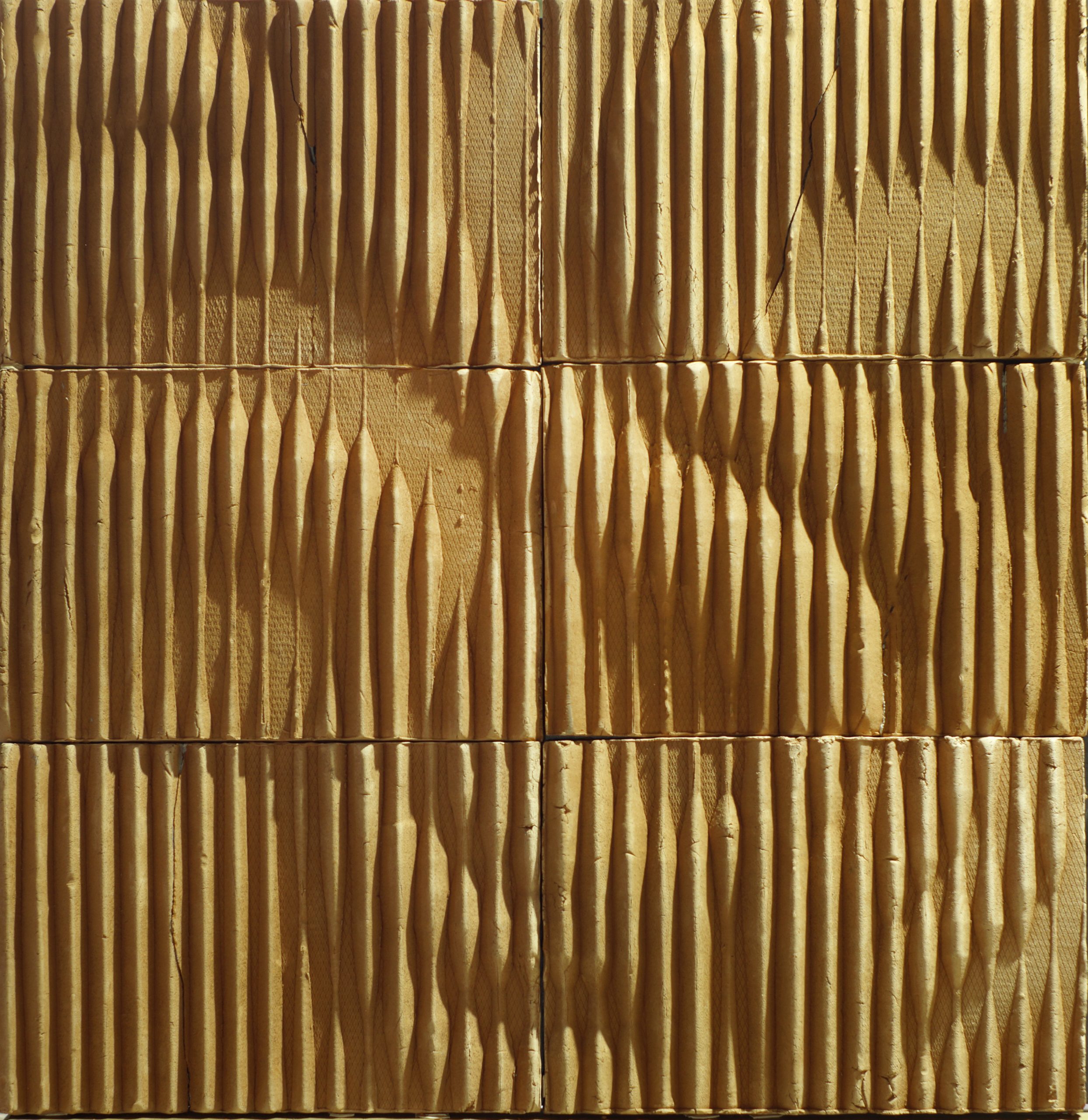
In the early stages of the panel design, the robotic fabrication process has to be taken into consideration. For this instance, a hotwire is used to cut out the mold out of polystyrene blocks. Particularly, the hotwire shape is set to be an isosceles right triangle, oriented in a vertical plane, with the hypotenuse on the upper side and the right angle at the bottom. This information influences the panel design regarding the relief i.e. the grooves, their depth, width and flow. In order to have more control over the design, the groove depth is influenced by an image sampler component. This means that the grayscale pixel intensity controls the depth of the grooves. The chosen image depicts a traditional floral ornament, specific for the Banat region. In order to explore fabrication capabilities with the hotwire tool and determine the bounds of the parameter values, three case studies were conducted. Each case study had the same reference image, but the groove’s flow and width were changed.
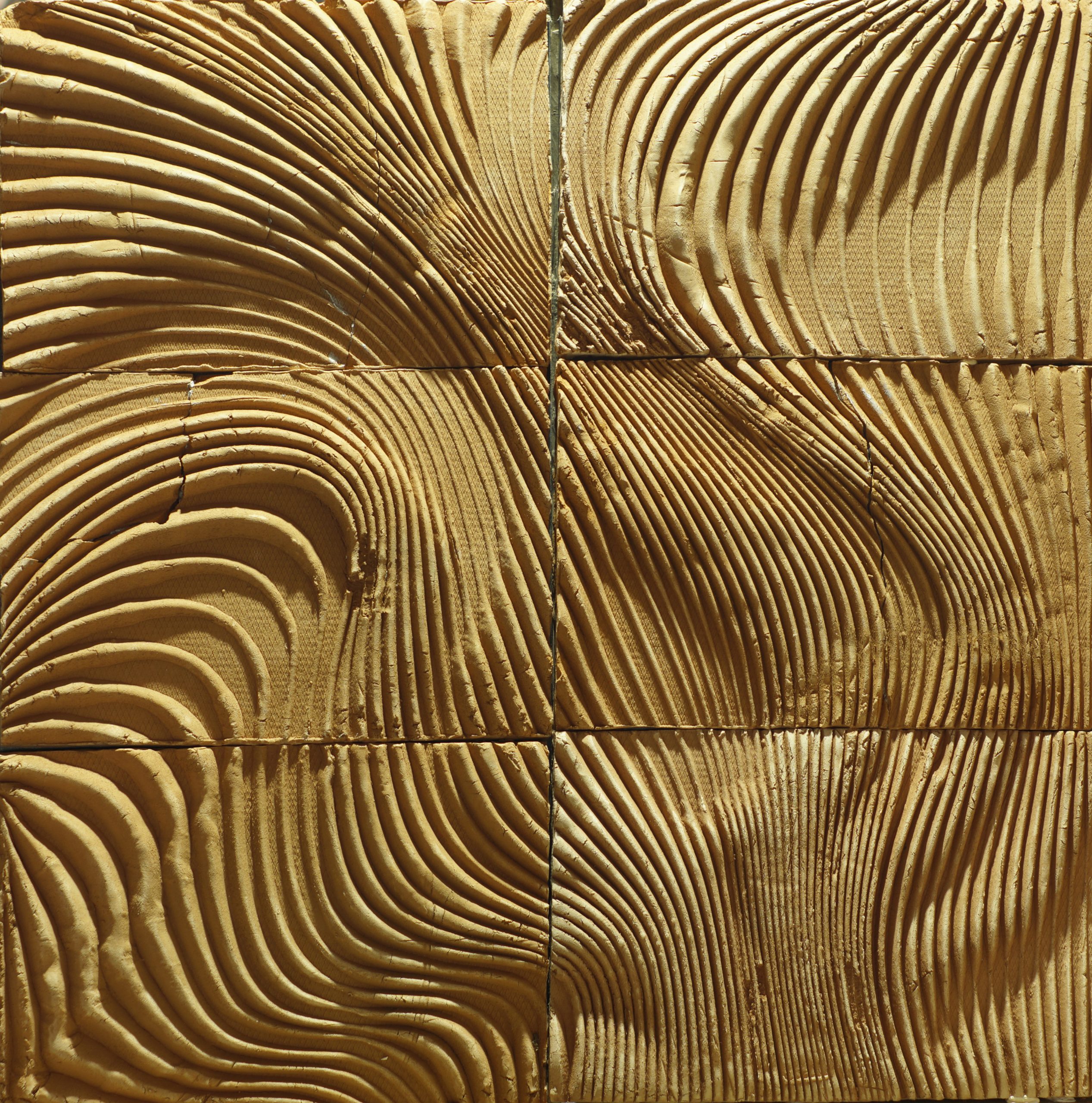
In the first case, the groove flow lines were drawn in parallel with the vertical border edges of the entire installation. The other two cases had a profound fluent appeal, where the second case focused on using flow lines that follow the contrast of the reference image, while the third case had a set of flow lines that were going disjointed from the reference image. The hotwire profile is set to follow these lines, oriented perpendicularly to the tangent at a specific point. This approach is used in the first case, given that the distance between the parallel lines is constant. However, in the other two cases, the distance between certain portions of the curves varies, which would mean that the groove width could be smaller than the hotwire profile width. Given that the depth is influenced by the image sampler, it is not possible to control the width in this manner. This is why a viable solution is rotating the hotwire profile about a vertical axis located at a certain portion of the flow lines, especially in the areas where the curves are getting too close to one another. This results in the larger inclination of the groove’s sides, meaning the sides are steeper when compared to the sides of the first case scenario.
After generating an aesthetically appealing result, observed through a 3D model, the fabrication preparation phase is necessary to instruct the industrial robot as to how to move with the hotwire profile to procure a similar 3D model.
This phase follows the logic of the aforementioned approach, in terms of using the orientation and position of the hotwire profile to drive the model generation. Given that the model generation refers to a real physical model, a transition from a virtual to a real world environment needs to occur. In order to do so, it is necessary to generate a set of instructions that the robot can follow. The instructions are written by using “targets”. Targets represent both the position and orientation of the end effector of the industrial robot arm, which carries the hotwire profile tool. By using inverse kinematics, it is possible to calculate the angles in the industrial robot joints as it moves from one target to the other. Additional targets had to be added to the existing ones on the flow lines in order to allow the hotwire tool to exit the polystyrene block that it is cutting and enter the block at a new location. This phase also entails simulating the robot in order to verify if all the targets are within the robot’s work area, if all the joint angles are within the proper domains and that there are no collisions between the robot with itself and the surrounding.
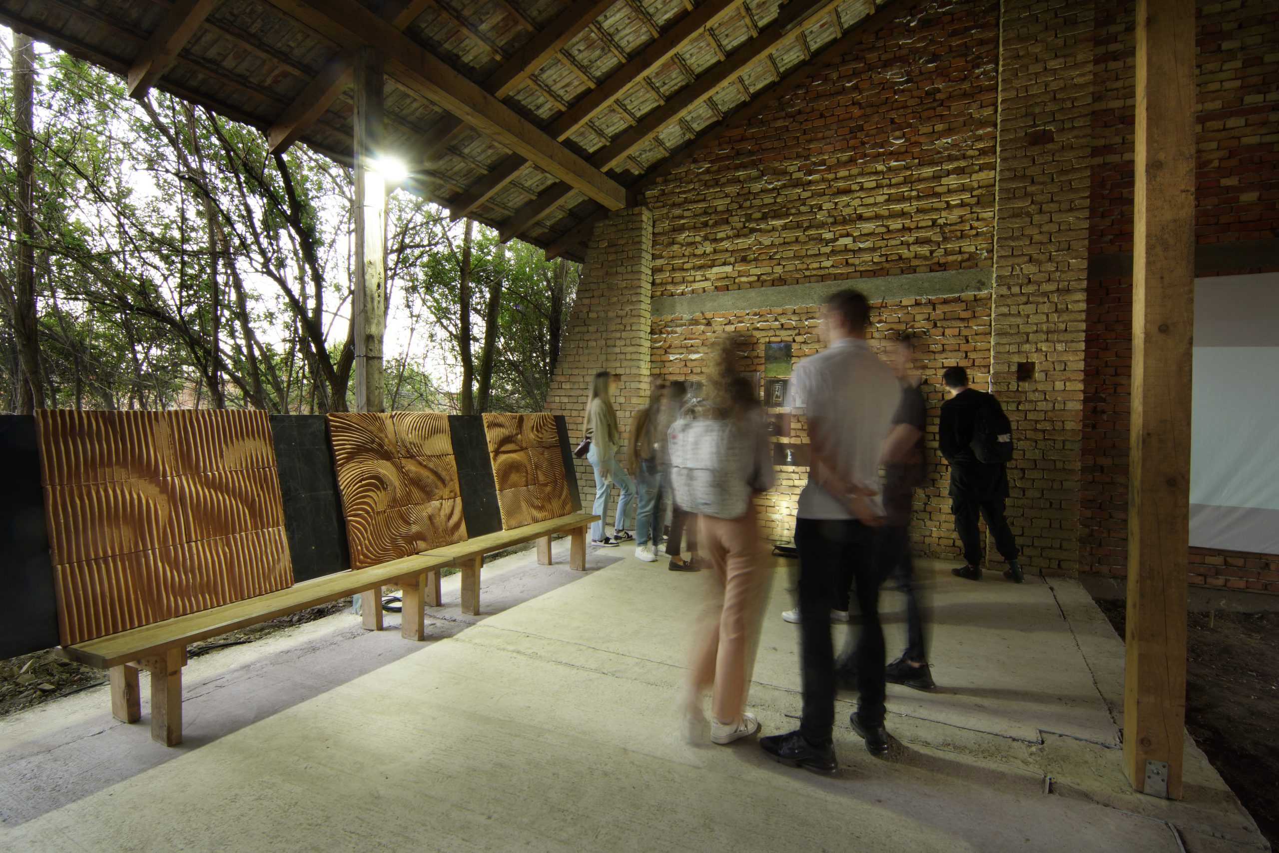
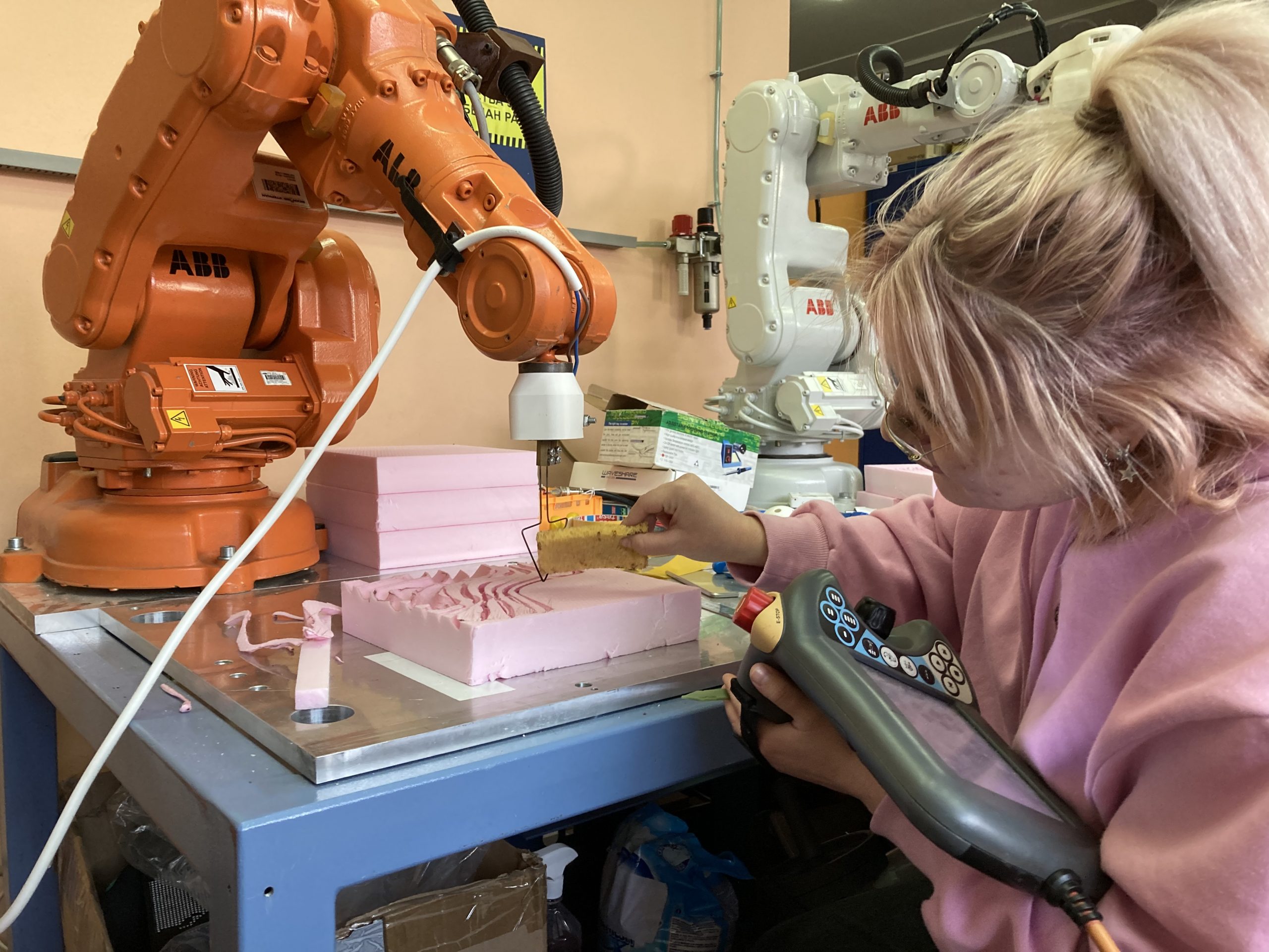
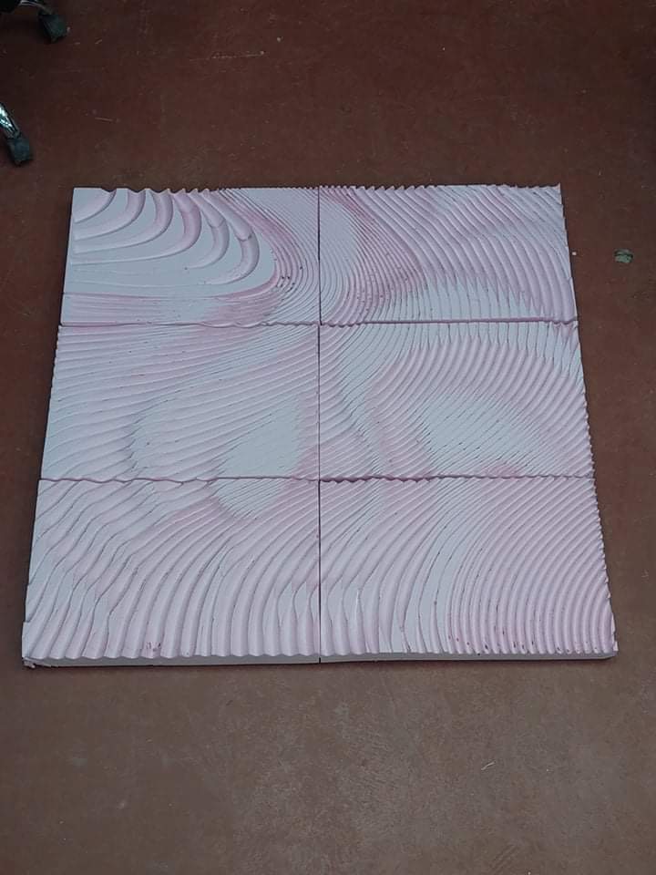
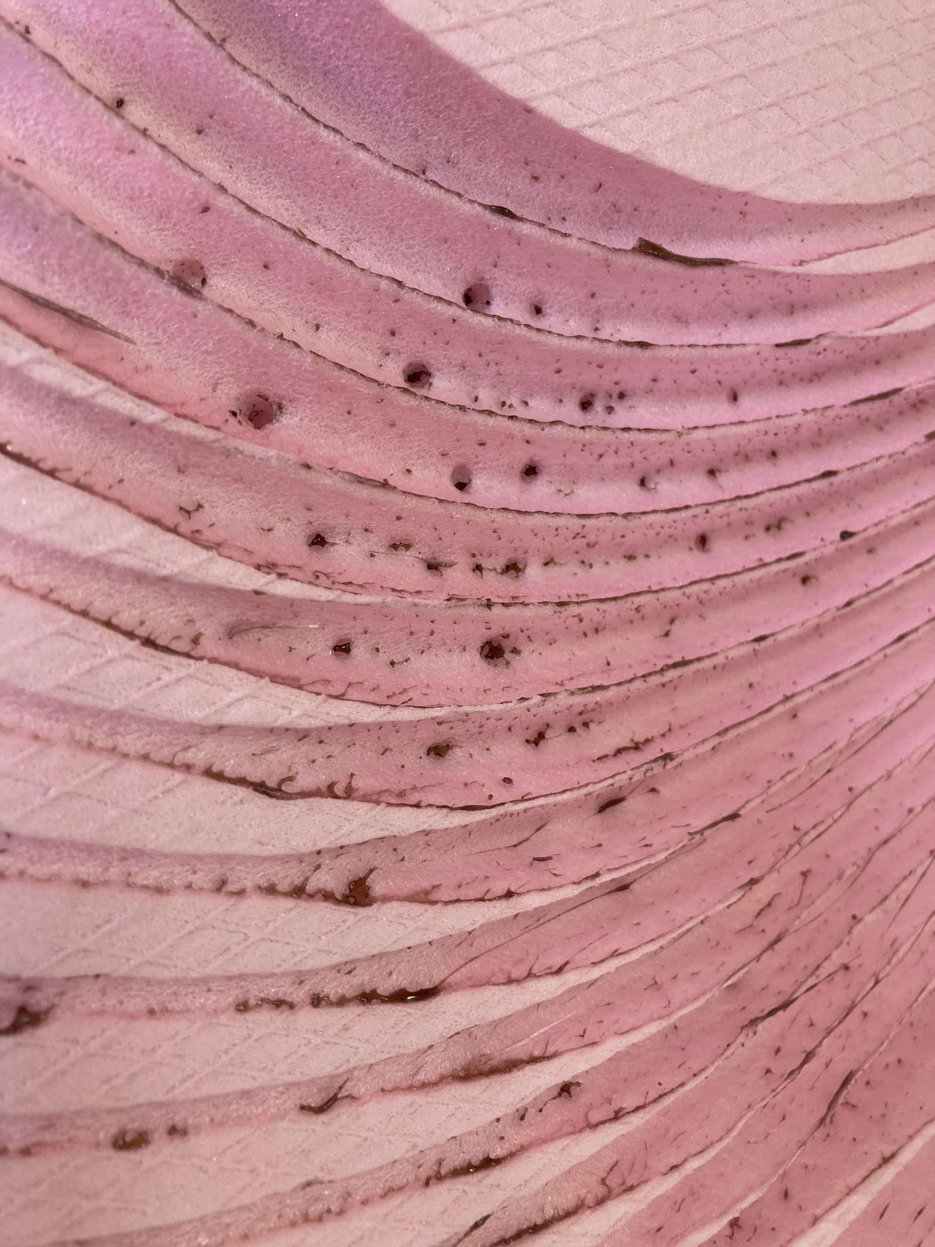
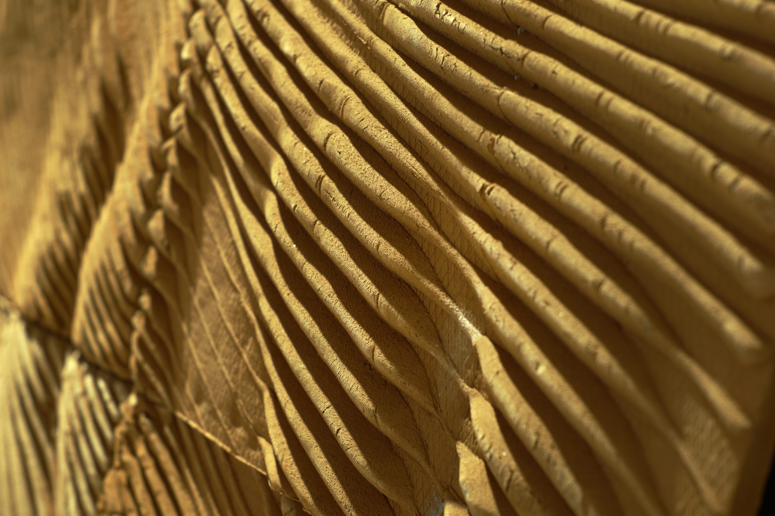
The third phase covers the polystyrene mold fabrication. Polystyrene blocks, 5 cm thick, were chosen for this task, out of which 50x33cm panels were cut out. The panels were oriented in front of the industrial robot arm, on a horizontal table so that the hotwire profile tool can access it on the upper side. The hotwire temperature is set from 300 to 350°C, with the speed being between 5 and 10 mm/s depending on the contact area and the material. These parameters are changed manually. Given the fact that the hotwire radiates heat, The residual temperature influences the generation of artifacts, which are seen as curled up ends of the grooves’ sides. The existence of artifacts is undesirable, since their shape is concave with respect to the direction of the clay extraction from the mold. This makes the clay casting process difficult, which is why these artifacts are sanded off the grooves. Once the grooves are prepared for clay casting, the panel sides are boarded up in order to shape the border adequately.
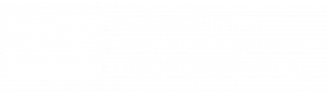
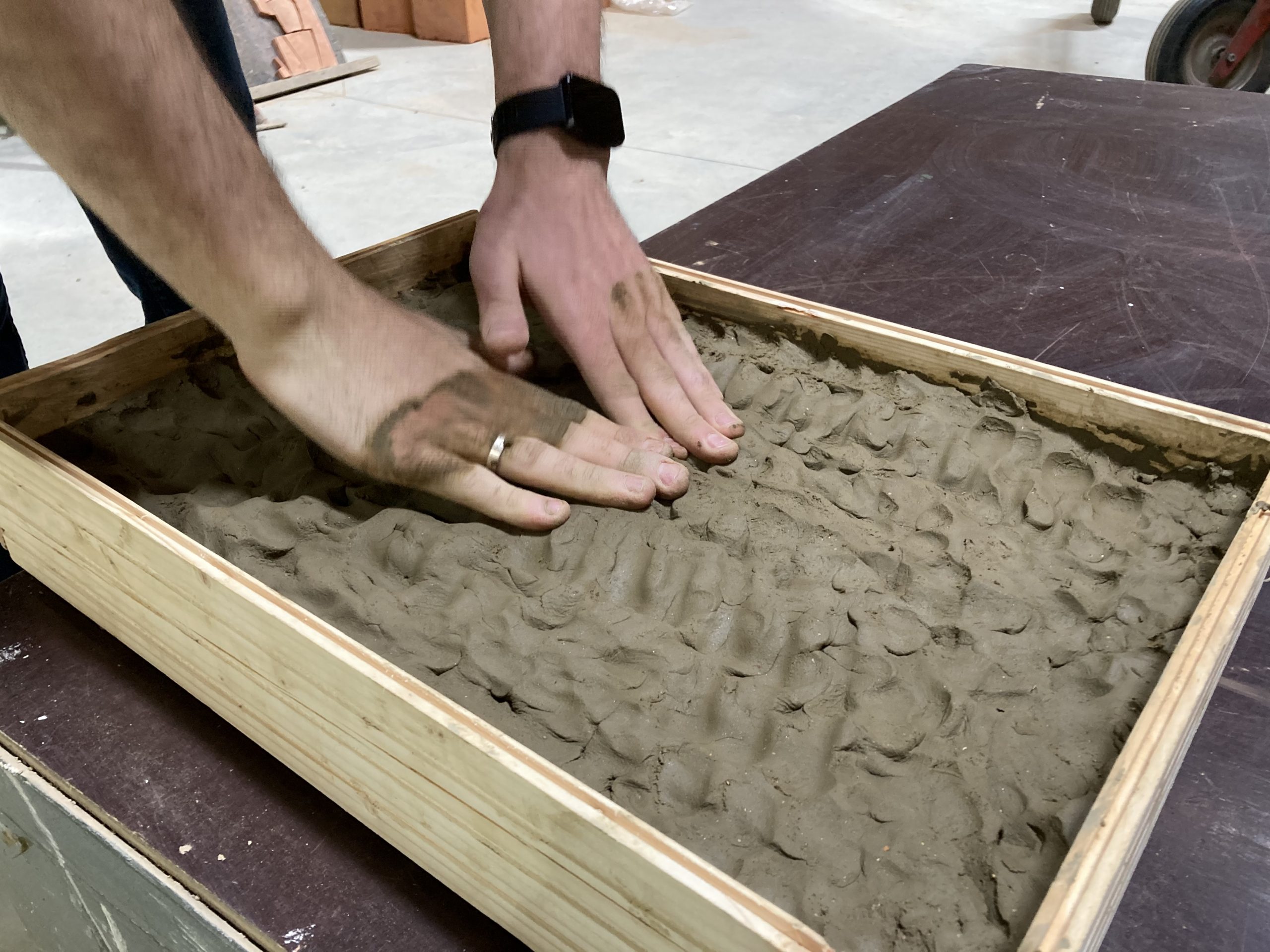
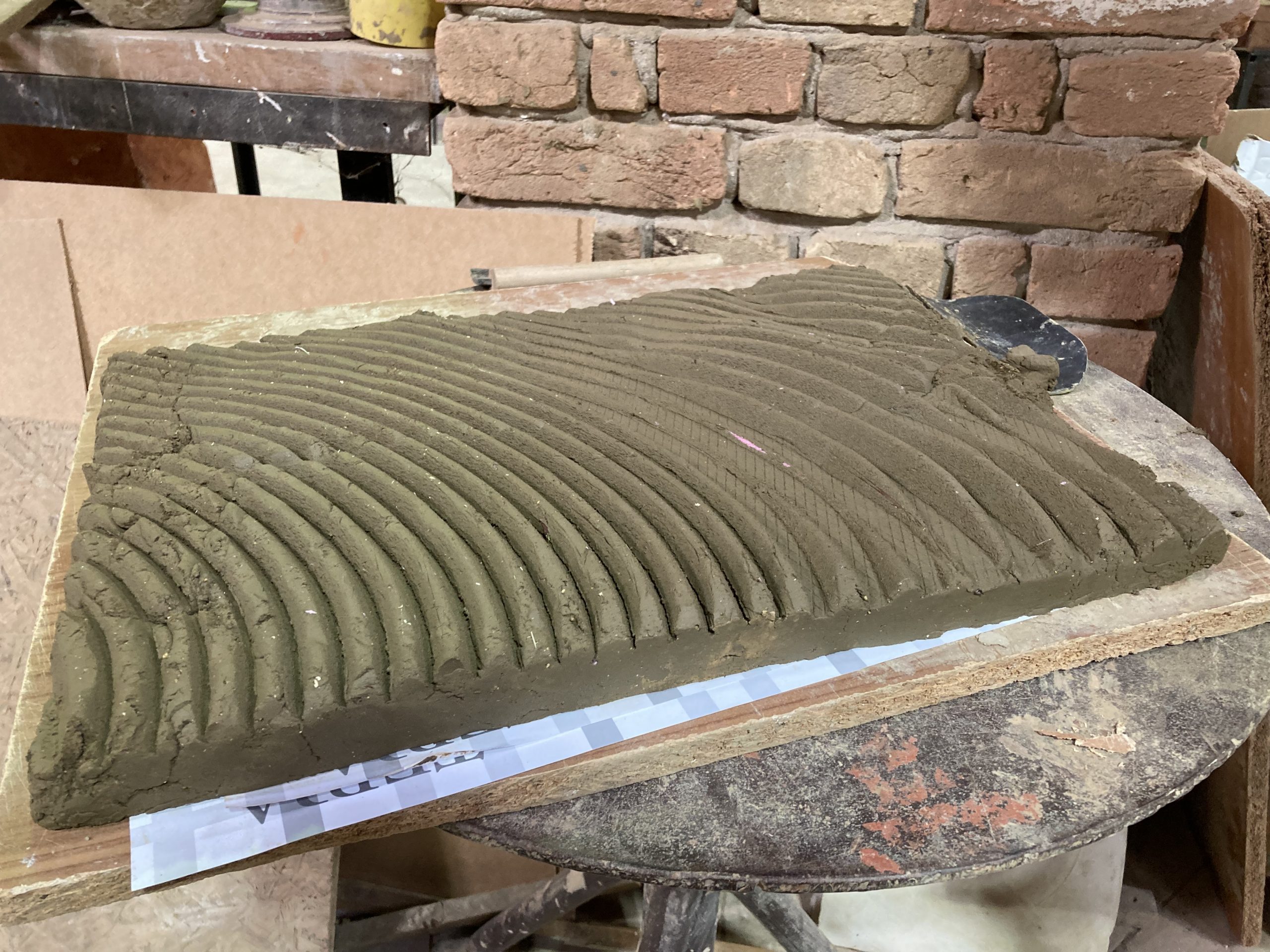
In the last phase, the emphasis is placed on the clay, starting with embedding the clay into the mold. If clay is embedded in pieces, the formation of cracks can occur due to the properties of the material. This is why prior to the embedding process, the clay is pressed into a shape resembling a pancake, with constant thickness of 2cm, out of which the necessary dimensions of the panel, 50×33 are cut out. After embedding this piece of clay, additional clay is added in order to procure a thickness of 3 cm in total. In order to make the process of clay extraction more efficient, sanded pieces of terracotta are dusted on the panel, prior to the embedding process. Immediately after the embedding process, the side boards are removed and the embedded clay is extracted from the mold. The clay panels are left to dry for around two weeks in conditions of constant temperature and humidity, to remove excess water from the clay. This process is necessary due to the final step, which is baking them in a furnace at 980°C for 48 hours, where any excess of water can produce steam and explode the clay element inside the furnace. Once the panels are baked, they are ready to be placed on the wall as an interior panel.
Text and Media: Marko Jovanović and Marko Vučić