O1.M3.03 Computational design in architecture: brick case study
Free
About this course
Chapter 1. The role of brick and clay in the history of architecture. Short overview.
Teaching method: lecture
Duration: 10 min
Brick is one of the oldest known building materials used for more than 9,000 years. From the very beginning of use until the digital age, brick is still one of the favorite materials used by architects. Brick architecture appeared all over the world in regions with warm climates where it could be dried in the sun for hardening. Brick was the main material for the first cities and civilizations in Mesopotamia, Ancient China and Indus Valley Civilisation. Ancient cities such as Çatal Höyük in Turkey (70 century BC), Mohenjo-Daro in Pakistan (25 Century BC) shows us that most of the manufacturing techniques were already known 4 millennia ago. Brick making was a major mesopotamian industry and main building material for buildings and water supply systems in Mohenjo Daro and other Harappa valley cities (Khan and Lemmen, 2013). Moreover, some of the masterpieces of brick architecture such as Sumerian Ziggurat of Ur in Iraq (21 Century BC), Taq Kasra (Arch of Ctesiphon) in Iraq ( 272 BC- 540 AD) Basilica of Maxentius and Constantine in Rome (320 AD) were wonders of masonry construction for centuries and its structural and manufacturing logic has been repeated and further developed. Region of the Pannonian basin also had a long tradition of brick architecture. In the region of present-day Banat, The Ancient Romans introduced bricklaying techniques and manufacturing fire clay bricks. Romans legions used mobile kilns so they could make bricks throughout their empire. Influence or roman brick in European architecture still exists. Although new materials such as reinforced concrete and glass dominated in the 20th century, brick has retained its position as a favorite material among architects who advocated regional architecture and local materials. For Alvar Aalto and F.L. Right understanding brick logic can turn architects into magicians that are able to transform worthless brick into precious architectural objects (William Hall, 2015). In the past two decades digital technologies have influenced re-thinking design with brick through novel material, structural, design and manufacturing strategies.
Chapter 2. Notion of Digital Brick approach. The use of digital design and fabrication tools to enhance brick-based design thinking.
Teaching method: lecture
Duration: 30 min
As is the case with other building materials, brick as well as other clay based materials has peculiar material, structural, manufacturing and design logic. Clay based material such as brick, tiles and terracotta panels are natural, durable and environmentally friendly material. Understanding the basic ingredients of brick logic as well as computational design and digital fabrication strategies can change how we can use such common material in architecture. Notion of a Digital Materiality was coined for the first time by pioneers of robotics in architecture Fabio Gramazio and Mathias Kohler (Gramazio and Kohler, 2008) and it can be described as an interplay between data and material, design and construction process controlled in all its details by the architect (Willmann et al., 2013). New design paradigm shift has been recognized by many other contemporary architects and they developed similar approaches in the intersection of digital technology, material science, and digital manufacturing. Neri Oxman, coined the term Material ecology which „brings together materials science, digital fabrication technologies, and organic design, to create new possibilities for the future“ (MoMA exhibition 2020). Similarly Rippmann introduced the new methodology for „structurally informed design“ based on relation between relation between form, forces and fabrication (Rippmann, 2016) and Pottmann coined the term fabrication-aware design (Pottmann, 2012) that pertains with optimization processes of freeform shapes for feasible and rational design, based on material and geometry constraints.
In the same manner, the concept of digital brick can be understood as a new way of understanding the logic of brick, which arose from the application of digital technologies in creating new ways of brick-thinking. Through several examples, new ways of thinking through new materials, structural, production and design logic are further explained.
Chapter 3. Re-thinking material logic of brick and clay
Teaching method: exemplification, case study
Duration: 40 min
Material logic can be described as a common way of understanding the mechanical and perceptual qualities of a material. An example of the usual way of thinking about materials is that wood cannot be bent and shaped by hand, as is the case with rubber. Such a way of material logic was a common way of thinking. However, digital fabrication technologies have influenced changes in how we think about the materials. The Dukta product is one of the examples of how wood can get elastic and textile properties by applying CNC cutting technology with a unique incision process. The different incision patterns can open new horizons in using flexible wood due to new features like transparency and sound absorption. In a similar way, robotic production of parametric brick walls radically changes our perception of brick bond patterns. Gantenbein Vineyard Facade, (Gramazio & Kohler, 2006) is the first realized project that changed our perception and tectonic properties of brick walls, changing the way we think about brick bonding. From then, many other projects including The brick installation “Structural Oscillations” for Venice Biennale (Gramazio & Kohler, 2007) or Administrative Building Textilverband in Münster (Behet Bondzio Lin Architekten, 2018) reflects different material logic of brick that more resembles to textile surfaces than flat brick walls.
Chapter 4. Re-thinking structural logic of brick
Teaching method: exemplification, case study
Duration: 40 min
Structural logic of brick reflects its mechanical properties. Brick masonry has good compression strength but is very weak in tension because it is composed of two different materials, brick and mortar and the bond between them is weak. For this reason brick masonry is expected to resist only the compressive forces. Ancient builders were familiar with these properties of masonry structures and brick has been used for centuries as a material for making vaults and domes. Historically, hanging models have been used to design vaulted structures. Consequently, cylindrical and rotational surfaces derived from funicular curves prevealed as a form of brick shells. In the last two decades, the rise of computational design and digital form-finding methods such as Thrust Network Analysis (TNA) have enabled a new language of doubly curved brick shells. To explore the design space of funicular shapes, the TNA method was implemented as an interactive, digital tool, providing the user with a high level of control over the force distributions in a funicular network, in order to accomplish a certain design goal. The new digital form finding tools such as TNA based RhinoVault or spring-relaxation based Kangaroo-Grasshopper, significantly change the way how we can design structurally informed brick shells in architecture.
Chapter 5. Re-thinking design processes with brick
Teaching method: exemplification, case study
Duration: 40 min
Design logic is based on the application of design tools, models of thinking and models of representation in order to solve specific problems. For centuries design logic in architecture was connected to the use of thinking models and tools for paper-based representation as well as making physical models. In the second half of XX century early CAD systems tried to mimic already known drawing techniques and attempt to depart from paper-based media by speeding up and augmenting the design process. While the algorithmic way of thinking was already known to some academic circles of architects, engineers and artists, revolution in digital design thinking was initiated with the development of the digital manufacturing process. Novel manufacturing processes were based on delivering digital CAD files directly to CNC machines, opening new possibilities in creating unique custom shaped objects that can be assembled with great precision. During the 90s Frank Gehry and Nikolas Grimshaw were among the first architects that recognized the potential of novel manufacturing processes used in aircraft, automotive and shipbuilding industry and they applied in architecture by creating parametric models to create a family of unique forms digitally controlled by geometric parameters and constraints. First parametric tools made a shift from drawing the single shape into the diagram that represents a family of shapes. New algorithmic based tools also made a shift from (brick) module to parameter, from element to component, from composition to rule.
Chapter 6. Re-thinking manufacturing processes with brick and clay
Teaching method: exemplification, case study
Duration: 40 min
Manufacturing logic pertains to common production techniques used in the process of construction and assembly. Brickwork techniques and masonry techniques have not had significant changes until the last 2 decades. Apart from some isolated regional techniques such as catalan vaulting that was frequently applied all over the Mediterranean, primarily in Spain, bricklaying was based on simple rules of brick bonding and skilled masonry workers. Novel manufacturing processes based on digital technologies or material processing significantly change brickwork logic. Research experiments started at Block Research Group (2010) continue exploration of manufacturing processes based on 6 centuries old techniques such as Catalan vault and combine it with innovative form-finding, falsework and construction methods in order to manufacture intriguing masonry vaulting with complex geometry. The new design and efficient construction approaches that expand language of shapes, use less material and falsework for construction than traditional approaches, has inspired many other projects, of which Bricktopia in Barcelona by Map13 and library for a school in Kopargaon, India by mumbai-based architecture firm sP+a is the best known.
The Manufacturing paradigm has also been changed in the field of assembly process. Started with bricklaying walls with industrial Robots at ETH Zurich by Gramazio and Kohler (2006), innovation in assembly process continues with flying robots for the installation Flight Assembled Architecture (Gramazio et al.,2011) and Augmented Bricklaying which reintroduces craftsmen into a digital fabrication process with the aid of augmented reality fabrication interface (Fologram, 2019; Gramazio Kohler Research and Incon.Ai, 2019 ). While all previously mentioned digitally based manufacturing process were based on standard cuboid brick shape, Research experiments Polybrick (Sabin Design Lab, 2014) and TerraForma (IAAC, 2017) investigate opportunities of using interlocking 3D printed components that has non-standard shape in order to create brick walls with increase structural and thermal performance through unique shape and cavities inside the brick. Interlocking shape of brick contributes better seismic behavior and mortarless installation.
Chapter 7. Computational design tools and brick based design strategies
Teaching method: lecture
Duration: 40 min
Computational design tools which can be used for clay based design strategies rely on parametric design. Parametric modeling and transformation rules are the core of the most generative design systems. The main benefit of such an approach is that this process replaces manual work and allows easy adjustments and changes.
The idea about using generative algorithms in architectural design has been around for a few decades. In the late 20st century one of the leading experts W. Mitchell classified modelling as: iconic, analogue and symbolic (Mitchell, 1978). By iconic modeling the building appearance can be observed and visualised. Analogue model would be a representation of a building property with a model, such as the one made by Gaudy for Sagrada familia to check the stability of the construction or the ones made by Otto Frey used to find the shape of the minimal surfaces. Symbolic models use numerical operations and building parameters (symbols) to describe the shape and other attributes. This type of modeling strategy will later develop into a parametric modeling based on visual programming.
In the beginning of the development, these systems were more oriented towards programming and were not easy to be implemented by designers. As different platforms evolved, the tools became more intuitive and adapted to the use in the CAD environment. Visual programming tools allowed programming to become easily accessible to the professionals in the area of design and hence became widely used.
Visual programming uses a programming language in the background while at the same time allows the user to describe the process by connecting graphical blocks instead using a typical text based programming. This approach is very suitable for visual environments such as CAD since all tools used for modeling can be replaced with a graphical block that is controlled by the input values. Due to this similar workflow the gap between visual programming and traditional modeling is very low. Visual programming environments can actually provide much more complex options for the design strategies and therefore inspire a new design paradigm based on the algorithm design instead of simple building 3D modeling.
Beside offering most of the tools available in the common 3D modeling environment, the visual programming environments with generative capability usually have a representation window which is directly connected to the modeling space. This connection allows that a user instantly has a visual representation feedback adjusted to the used input parameters (Celani and Verzola, 2004).
Although there is a great benefit of digital tools in general for the improved design process flexibility, the most interest in generative algorithms is rooted in digital fabrication. Numerically controlled machines allow variability of the design production without the additional cost, and mass customisation in architecture is developing in new ways.
When using the brick the concept of mass customisation is very beneficial. The variability can be introduced in several different ways. As it was mentioned before, material, structural, design process and manufacturing could be re-thinked in the frame of generative approaches. Adaptability of the process from the design to the final product is of great importance for the application of clay in architectural practice in a new way.
Different CAD environments can use different programming languages. In this course the Rhinoceros 3D and the visual programming environment Grasshopper will be used. Grasshopper contains most of the tools Rhinoceros 3D does, which makes the modeling logic similar, and users can easily copy modeling workflow to visual programming environment. Connecting the steps into a similar workflow is very intuitive and therefore programming skills are not required in order to use Grasshopper. There is also a great pool of additional plug-ins for Grasshopper available and these can be used to solve a variety of tasks not included in the original pack or can be just a simpler way to complete the same task.
7.1. Grasshopper tools
Teaching method: workshop
Duration: 240 min
Grasshopper is an extension of CAD program Rhinoceros 3D for visual programming (https://www.grasshopper3d.com). Algorithm created in Grasshopper is called definition and the main building blocks of each definition are parameters and components.
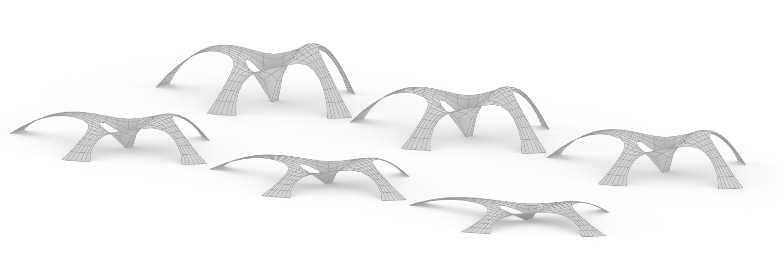
Basic parts of the Grasshopper interface are the menu containing parameters and components and the canvas. The canvas is the actual editor where the definition is created and edited (Figure 1a and 1b).
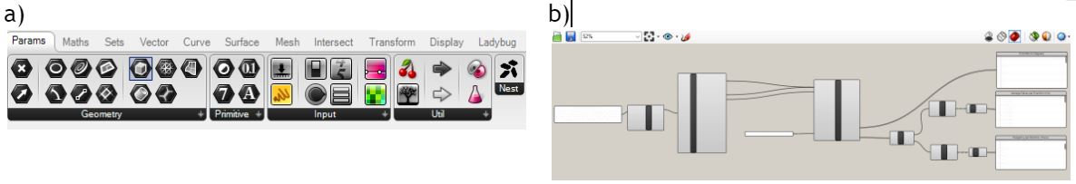
Figure 1. Parts of the Grasshopper interface. a) Menu with parameters and components. b) The canvas with definition.
Main Menu Bar is typical as in other similar programs. The tools are arranged into a Component panels grouped into Parameters (the group of tools that can contain geometry, values, input and utilizing tools), Math (the group of tools for mathematical operations and functions), Sets (group of tools for working with data sets and data trees), Vector (group of tools mainly focused on operations on points and vectors), Curves (group of tools dealing with creating curves and their analysis), Surfaces (group of tools dealing with surfaces and their analysis), Mesh (group of tools for mesh modeling and analysis), Intersect (the group of tools to analyze the relationships between geometric elements and/or shapes) Transform (group of tools for geometric transformations) and Display (group of tool that can ease the data visualization).
In each of these groups there are tools that can be dragged and dropped to the canvas. Another way to find a component is to search it in a quick menu. Either way when the component is at the canvas it can be connected with other components to create a definition.
Grasshopper interface also contains non-essential parts such as Canvas toolbar with frequently used tools, Status bar that provide feed-back on the selection set and other helpful additions.
Important feature of Grasshopper is that every geometry introduced in Grasshopper is visualized in Rhinoceros viewport windows. By default the geometry from Grasshopper appears red to distinguish it from the models made in Rhinoceros, and when the Grasshopper component with a geometrical object is selected the component will turn green. A Grasshopper definition consists mainly of Parameters and Components. Parameters contain data and Components contain actions. Each component has at least one input parameter and most of them have one or more outputs. Plug in place on the left side represents the input, and on the right side are output. The input data can be defined within the component or inherited from another component. Each component has a context menu which contains most features linked to the action, such as preview, enable and bake.
Components can be dragged and placed on canvas, and connected with each other with wires in an intuitive way. Wires can be visually different depending on the type of data which is transferred from one component to another. If there is one value in the data stream the wire will be presented with a simple line, if there is numerous data in a single stream the wire will be thick or dashed depending on the data arrangements.
Grasshopper allows conditional connection of the components, so the whole definition flows from left to right. Loops can be created only with the use of additional programming of plug-ins. In the architectural modeling workflow most of the definitions do not need loops since the repetitive tasks usually depend on the designer not an external user and the number of repetitions is known in advance. Such repetitive tasks therefore can be solved by the use of the lists that determine the repetition. If the task has to be repeated several times, all data can be gathered in a single stream, and the task will be applied to all. This allows the definition to be created completely within Grasshopper provided tools without the need for additional extensions.
Scalar components are aimed to solve calculations and other numerical tasks that are needed in a definition. These components include numeric data, constants and intervals, operators which perform basic calculations on input values, conditional statements that can compare input values, functions and booleans.
Conditional statements, functions and booleans are often combined with the Dispatch component. This component dispatches the list of values according to a true/false pattern. Therefore, various conditions can be applied into a definition to select data according to a criteria.
Vector components in the Grasshopper are mainly used to work with points and basic transformations. Vector is actually the same as the point in Grasshopper workflow.
Manipulation and analysis of vectors/points considers tools such as calculation of a distance between points, decomposition of composition of a point/vector (output or input values are x, y and z coordinate of a point/vector), vector angle or length, summation of vectors, creation of a line/vector between two point or vectors, etc. Basic transformations include move, rotate, scale and others.
One of the most important features in Grasshopper is building and manipulating lists. Grasshopper allows having a combination of a higher number of lists stored as inside a single parameter and therefore perform operation on the multiple values/lists at once. Data trees are very important when working with Grasshopper because by understanding data structures, users can avoid repetition of an action and save time and computation power.
In order to be able to select the data within a list, an index has to be assigned to each value in the Grasshopper list. Index numeration is matrix based, so technically it is not an index but a path that can consist of multiple values. Data trees can be compared to a folders structure – there are parent lists and sublists, and their relationship is defined by path numeration.
Matrix based list path numeration in Grasshopper is a base for a hierarchical data tree structure, which means that it allows data to be easily divided into branches.
Data trees can be made by combining input values or intervals, or can be output of a component. If the data stream contains a list, the visual appearance of a wire will change to a thick line, and if the data stream contains multiple lists a wire will be represented as a dashed line to help the user to follow the data flow inside the definition.
Grasshopper offers many tools to work with trees or to analyze tree statistics. Data trees can be flatten, grafted, simplified or flipped. Path mapper component allows more complex changes on the data tree paths. For each list a specific item can be called by the path or by the value, the list length can be extracted, the list can be reversed or shifted by a certain number of places, the list can be split, culled, waved or dispatched.
Clear structures of the data trees are very important, since complex definitions will not work properly if the data mismatch in any component.
For the interpretation of a bitmap image, the “Image Sampler component” is very important. Pixels values of the image can be transformed in a geometrical or numerical data, which can further be used to fabricate a panel that resembles the bitmap image.
Input data are the set of points and pixel values in these points. Usually the set of points is sort of a grid, but it does not have to be. Any list of points can be used as long as the relative position related to the width and height of the image in pixels is inserted.
For each point an output value can be extracted. This value can be color RGBA, red, green or blue value, hue, saturation or brightness or transparency.
Other Grasshopper components can be used along with the Image Sampler to manipulate the image data stream without changing the bitmap image. For example brightness and contrast values could easily be changed by Graph Mapper without the need to make adjustments of the bitmap image tones.
7.2 Design strategies: self-supporting structures, brick tiling, image based brick patterning and rotation
7.2.1. Computational method for form-finding compression only vaults.
Understanding the equilibrium of structures in unreinforced masonry is primarily a problem of stability. In 1675 Robert Hooke described the relationship between a hanging chain, which forms a catenary in tension under its own weight, and an arch, which stands in compression, but he couldn’t derive an equation of catenary. Culmann (1866) and Poleni (1988) adopted these ideas and developed graphical analysis as a powerful method for equilibrium analysis in structural engineering. However, only few architects employ such approach in predigital age, since that such process of analysis was time-consuming and tedious.
In the last 25 years, several three-dimensional computational methods have been developed for interactive shell design. Kilian (2005) developed a virtual interactive hanging string modeling environment based on particle sprint systems. Ripmann et al. (2012) advanced another method based on Trust Network Analysis and graphics statics. The method presented used as a study case in this course is based on projective constraint-based solving method (Cuvilliers, 2020) made available to wider audiences and CAD community known as a Kangaroo 2 solver for Grasshopper 3D Rhinoceros Software. At each iteration, the Kangaroo 2 solver moves closer to the equilibrium position by projecting the positions on the sets of constraints representing the relationships between them. The solution is a physical equilibrium with correct derived forces, if the constraints are physically accurate (Cuvilliers et al., 2018). Kangaroo 2 algorithm resembles the kinetic damping of dynamic relaxation, resetting the vertices’ velocities when the forces change direction, but using forces derived from the projective constraints method. Design of compression only shells with Kangaroo 2 solver is based on following steps:
-
- design of planar discrete mesh,
- setting constraints,
- digital form finding.
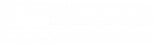
Planar discrete mesh will be used to generate projected compression-only shells whose edges form a funicular network. The next step is making a planar closed curve in such a way that inside the curve there are mesh vertices that can be projected as shell openings (Figure 2).
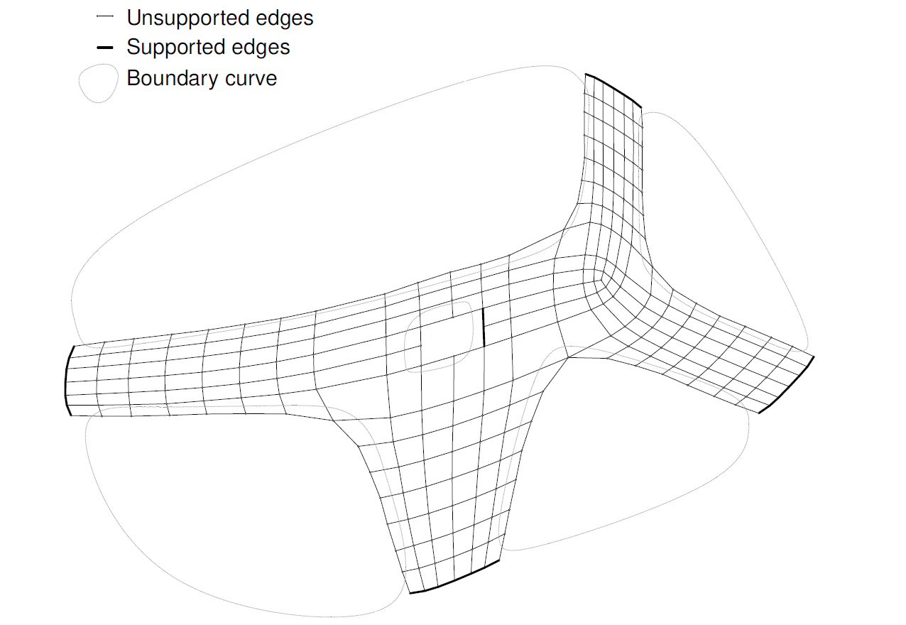
Figure 2. Design of compression only shells.
There are three types of constraints used as an input for Kangaroo 2 solver and all constraints have previously described weights that control the relative importance. Those constraints are: supported vertices (mesh vertices that remain fixed during the form-finding process), edge length (factor that controls length of the edges) and Load (Z axis vector that controls the shell form under different influence of loads). Interactive design of compression only shells are described in figure 1b with visual algorithms. Different design solutions can be achieved with simple control of Loads, Edge Length factor and creating different sets of non-supported vertices. Form variation controlled by different influences of loads are given in Figure 3.
Figure 3. Equilibrium position under the different influence of loads.
7.2.2. Computational method for creating parametric brick wall
During the 70s French Artist Jean Pierre Yvaral developed a numerical method for converting images into abstract compositions. The most famous works of this method were based on variations of Merlyn Monroe’s face. Yvaral coined the term ‘Numerical Art’ to describe painted two-dimensional artworks that were composed according to numerical algorithms and rules (Yvaral, 2012). Similar to halftone printing techniques, numerical art is a way to create the appearance of an image based on pattern. Contrary to the halftone pattern, Yvaral’s numerical art is based on affine transformation of geometric shape used for creating patterns that resemble images. Three decades later, architects Fabio Gramazio and Mathias Cohler used a similar approach to convert image into a set of rules for brick rotation and robotic bricklaying in such a way that shadows of rotated bricks create abstract composition based on referenced image. The method and results can be described with a visual algorithm shown on Figure 4.
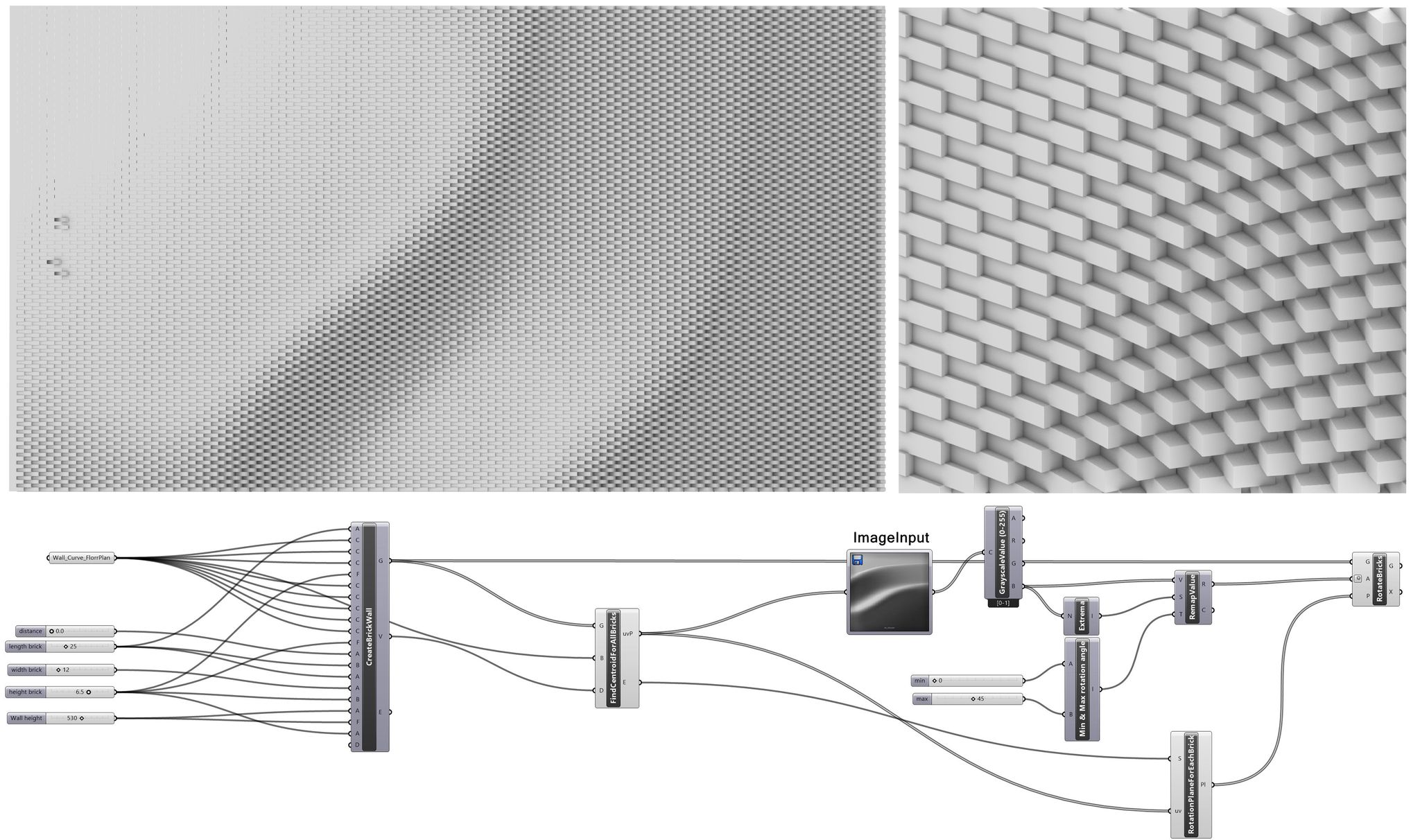
Figure 4. Design of brick wall based on “Numerical Art” method.
References
References
- Willmann, J., Gramazio, F., Kohler, M. and Langenberg, S., 2013. Digital by material. In Rob| Arch. pp. 12-27. Springer, Vienna. doi: 1007/978-3-7091-1465-0_2
- Neri Oxman Material Ecology Exhibition 2020, MoMA, https://www.moma.org/calendar/exhibitions/5090, accessed june 2022.
- Fabio Gramazio and Matthias Kohler. Digital Materiality in Architecture, Lars Müller Publishers.
- Khan, A., & Lemmen, C. 2013. Bricks and urbanism in the Indus Valley rise and decline. arXiv: History and Philosophy of Physics.
- William Hall. 2015. Brick, Phaidon Press.
- Rippmann. 2016. Funicular Shell Design: Geometric approaches to form finding and fabrication of discrete funicular structures. ETH Zürich.
- Pottmann, H., 2012. Freeform architecture and fabrication-aware design. Computers & Graphics, 36(5), p.306. doi: 1016/j.cag.2012.04.003
- Yvaral: Progressions. 1 August – 14 September 2012. Exhibition catalogue held at Alon Zakaim Fine Art’s Dover St gallery.
- Mitchell, W.J., 1975. The theoretical foundation of computer-aided architectural design. Environment and planning b: planning and design, 2(2), pp.127-150. doi: 1016/0010-4485(76)90172-X
- Celani, G. and Vaz, C.E.V., 2012. CAD scripting and visual programming languages for implementing computational design concepts: A comparison from a pedagogical point of view. International Journal of Architectural Computing, 10(1), pp.121-137. doi: 1260/1478-0771.10.1.121
- Grasshopper official website, https://www.grasshopper3d.com/, accessed june 2022.
- Culmann, K. 1866. Die graphische Statik. Zürich : Meyer und Zeller.
- Heyman, J. and Poleni, G., 1988. Poleni’s problem. Proceedings of the Institution of Civil Engineers, 84(4), pp.737-759.
- Kilian, A., and Ochsendorf, J., Particle-Spring Systems for Structural Form Finding, Journal of the International Association For Shell And Spatial Structures, 2005, 46(2), 77–85.
- Rippmann, M., Lachauer, L. and Block, P., 2012. Interactive vault design. International Journal of Space Structures, 27(4), pp.219-230. doi: 1260/0266-3511.27.4.219
- Cuvilliers, P.P.E., 2020. The constrained geometry of structures: optimization methods for inverse form-finding design (Doctoral dissertation, Massachusetts Institute of Technology).
- Cuvilliers, P., Yang, J.R., Coar, L. and Mueller, C., 2018. A comparison of two algorithms for the simulation of bending-active structures. International Journal of Space Structures, 33(2), pp.73-85. doi: 10.1177/0266351118779979
Other Instructors

Bojan TEPAVČEVIĆ
Associate Professor
Marko VUČIĆ
Assistant Professor

Marko JOVANOVIĆ
Assistant Professor
Ivana BAJŠANSKI
Assistant Professor
Vesna STOJAKOVIĆ
Associate Professor
Syllabus
The aim of this course is to master the basic understanding of the computational design tools and its application in architecture. Computational design tools change the way we think about architecture and have profound effects on the construction industry. Within this course, special topics in the field of computational design will be addressed, with the focus on brick as a local material of the Banat region. Through various case studies of computational design based on the application of brick design and building techniques, the course will cover different approaches to innovative design.
O1.M3 INTERPRETING AND WORKING ON HERITAGE OBJECTS IN THEIR LANDSCAPE
O1.M3.03 Computational design in architecture: brick case study
Type of format
Lecture & workshop
Duration
60 min lecture (theoretical notions) 15 min break 40 min workshop (case study)
Possible connections (with other schools / presented topics)
FAUT O1.FAUT / Digital mapping heritage DEB O1.DEB / Small scale intervention
Main purpose & objectives
The main purpose of this class is to help students understand how local traditional materials can be used in a novel way, by applying contemporary design and construction techniques. Brick is one of the oldest building materials. Its application has been seen as a construction material in a pretty conservative way, as part of a load bearing or partition wall, as part of a vault or floor tiling. As such, it allows for tiling on flat surfaces or a self-supporting structure. However, in this exploration module, the emphasis is placed on several areas of interest: ● Design strategies for creating parametric brick patterns ● Design of compression-only masonry structure
Skills acquired
Detailed theoretical knowledge about contemporary design approaches. Basic understanding of main strategies for computational design based on Grasshopper3D tool, as well as specific Grasshopper add-ons including Kangaroo. The ability to recognize and interpret different material and geometry based design patterns related to contemporary brick design.
Contents and teaching methods
1. The role of brick and clay in the history of architecture. Short overview. 2. Notion of Digital Brick approach. The use of digital design and fabrication tools to enhance brick-based design thinking. 3. Re-thinking material logic of brick 4. Re-thinking structural logic of brick 5. Re-thinking design processes with brick 6. Re-thinking manufacturing processes with brick 7. Computational design tools and brick based design strategies: 7.1 Grasshopper interface, parameters and components, scalar components and vector components, Lists and branches, image sampler, Kangaroo solver 7.2 Design strategies: self-supporting structures, brick tiling, image based brick patterning and rotation.
Reviews
Lorem Ipsn gravida nibh vel velit auctor aliquet. Aenean sollicitudin, lorem quis bibendum auci elit consequat ipsutis sem nibh id elit. Duis sed odio sit amet nibh vulputate cursus a sit amet mauris. Morbi accumsan ipsum velit. Nam nec tellus a odio tincidunt auctor a ornare odio. Sed non mauris vitae erat consequat auctor eu in elit.
Members
Lorem Ipsn gravida nibh vel velit auctor aliquet. Aenean sollicitudin, lorem quis bibendum auci elit consequat ipsutis sem nibh id elit. Duis sed odio sit amet nibh vulputate cursus a sit amet mauris. Morbi accumsan ipsum velit. Nam nec tellus a odio tincidunt auctor a ornare odio. Sed non mauris vitae erat consequat auctor eu in elit.