
O1.M3.03.02 Digital fabrication for clay based structures
Free
About this course
Chapter 1. Integrated Design Approach
Teaching method: lecture
Duration: 20 min
During the Renaissance movement starting in the 14th century, the notion of individuals came into focus regarding almost every aspect of art and engineering. These individuals, also called master builders or uomo universale, propagated the approach of acquiring expertise in more fields of interest than just one. This kind of thinking paved the way to some of the greatest works of architecture, exploring proportions (Grafton, 2002) and dome construction (Brunelleschi and Battisti, 1981) to name of few. With one person being in charge of the entire building construction and having knowledge in various fields related to design and engineering allowed for the integration of all limitations, constraints and requirements thus producing a more comprehensive and informed design solution.
However, this practice was abandoned at the start of the industrial revolution in the second half of the 19th century. Huge advancements in building technology and material properties generated an excessive amount of information to be taken into consideration during design. This forced the master builder notion to be split into separate fields, such as architecture, mechanics, installation and civil engineering as several major ones. The existence of separate fields of expertise forced the design process to become disjointed, where the iterations and variations were being produced at a very slow pace. For example, the architect’s design was sent to be structurally analyzed, before being sent for installation integration, before determining the fabrication process and so on (Moe, 2008). If major concerns were raised in any of the stages, the design was returned back to the design phase, starting the cycle once again. Alongside the time-consuming nature of this approach, the cost-effectiveness was an issue, as well as loss of information while cycling between different fields of expertise.
One way of mitigating this issue was BIM – Building Information Modeling. Various experts were able to communicate and exchange their requirements and limitations with one another, thus keeping the information from being lost. What is more, keeping all the relevant data intact, made the exploitation phase much more durable and sustainable (Wong and Fan, 2013). However, the cost-effectiveness as well as the time-consuming nature of the design phase was still an issue with the constant back and forth between the stages and the experts. The integration of various experts within one common data environment (CDE) allowed for the exchange of information (Preidel et al, 2017), but at the same time, an early integration of all relevant data, making the approach cost-effective as well. A determining factor in the implementation of CDE was the use of computer aided software, especially the computational power that was increasing each year, mitigating the time-consuming portion of the approach. Even though the design and fabrication process was optimized, the design itself was based on a rigid and conservative appearance of box-like structures, following the library of BIM elements that had developed in the process. Furthermore, the performance of the building could be improved upon. The abundance of buildings such as this required the rethinking of the design process with the growing computational power to be utilized.
At the start of the 21st century, the organic and freeform structure movement experienced a resurgence. The main reason was the existence of digital tools and techniques which allowed the design and fabrication phase to be observed in another way. The design was no longer bound to “computerization” but to harnessing the full power of computer calculations – the computational design (Leach and Yuan, 2019). The use of algorithms – set of instructions – instead of finished functions in software allowed for the design to be iterative at a fraction of the time. The myriad of iterations allowed for optioneering (Gerber et al., 2012) but also for analysis and optimization, making the cost-effectiveness of the approach viable many times over. Finally, with the early implementation of all relevant requirements and limitations into one design algorithm, the master builder notation was again put forth. The design and fabrication phases were observed interdependently as an integrated design approach. Now the question was, can this approach be improved upon some more?
Chapter 2. Informed design
Teaching method: lecture
Duration: 10 min
With the integrated design approach being information dependent, the implementation of material properties in it was bound to happen. A myriad of approaches relying on the simulation of material properties to drive and optimize the final design solution occurred (Wortmann and Schroepfer, 2019). However, this did not utilize the full potential of the material exploration within algorithmic design. Here is where the new paradigm of Digital Materiality was introduced (Gramazio and Kohler, 2008) which stated that the focus was not placed on the material itself in correlation to the design, but on the comprehensive design and building process. A material informed design was introduced to explore this connection further and solidify its application for the foreseeable future (Gramazio et al., 2012).
However, the interwoven nature of the entire process required specific fabrication tools to be determined at the start of the design process. The introduction of the industrial robot set a new milestone back in 2009 (Gramazio and Kohler, 2009). The Gantenbein winery project utilized the precision of the industrial robot pertaining to brick laying and portrayed the versatile use of this fabrication approach, coupled with the informed model paradigm (Yunis et al., 2014). At this stage, the design process was fairly complex, integrating the design, material application and fabrication phases all at once, all through an algorithmic approach. A significant amount of expertise was required to produce the final solution, taking into consideration not just the fabrication process of using an industrial robot, but how the robot itself is operating. The robot end effector or the tool was taken into consideration as well, which influenced the design logic and hence drove the entire algorithm to take this information as a very important aspect of the integrated design phase (Pigram and McGee, 2011). Taking into account the aforementioned integrated design approach, coupled with the digital materiality paradigm as well as industrial robot fabrication approach, a very complex narrative starts to develop. Its potential can only be tested through real life explorations which are governed by such processes. One of such explorations can be observed in an emerging topic of digital ceramics.
Chapter 3. Digital Ceramics
Teaching method: exemplification, case study
Duration: 45 min
Vernacular architecture has always served as a model for contemporary architectural design. It represents a manner of establishing a deeper connection with nature by using traditional materials while being an integrated design approach of its own (Creang et al., 2010). One of these traditional materials is clay, a highly available, affordable and pliable material, which allowed for the masonry application to be as impactful as it was in the past and still is. By coupling clay with an algorithmic design approach, the notion of digital ceramics was born and explored through various projects (Sabin, 2010). As is stated, digital ceramics represents a practical medium for negotiating complexity in design. However, designing clay components and fabricating them cannot be observed to be disjointed from one another.
Subchapter 3.1 State of the art
The most obvious choice was to use adequately pliable clay, with specific hydration as to enable extrusion, similar to the extrusion of plastic from a 3D printer nozzle. This functional method of 3D printed ceramics was explored in great detail, with specific focus on the tectonics and tactile nature of the finished pieces (Van Herat, 2014). As the aforementioned industrial robotic fabrication came into practice, more and more end-effectors were developed to cope with the clay properties and various design logics that accompany it. This meant that an industrial robot can reliably extrude pliable clay and make it into a 3D structure (Kontovourkis and Tryfonos, 2018; Kontovourkis and Tryfonos, 2020). Given the industrial robot size and scale, larger ceramic components were possible to produce in such a way, albeit with necessary drying and baking afterwards. Still, given the versatile nature of the industrial robot, the exploration of the approach had even more potential. An industrial robot could provide a reference coordinate system – instead of the end-effector it merely carries the shape on which to print, making the process independent of support during printing and hence allowing perforation in the design (Anton and Abdelmahgoub, 2018). More fluent extrusion guidelines could be produced, given the change in the approach. The perforated nature of ceramic components made in such a way allows for the introduction of performance based design as well (Rosenwasser, 2017). The use of interwoven nature of clay extruded fiber-like strains allows for a porous looking panel that can be designed according to specific performance it needs to satisfy, such as insolation and air-flow. When reviewing these examples, the clay 3D printing approach is explored in depth, without exploring the topic of clay component fabrication laterally.
A different way of observing clay component fabrication came into practice with the notion of shaping a larger chunk of the material with different tools, instead of adding it through an extruder. This shift from an additive manufacturing approach to a subtractive one explored various shapes and forms that could be produced as a result. Clay malleability could be observed in sculpting practices, where the industrial robot takes the mantle of a “sculptor” using clay shaping tools to follow paths and produce interesting architectural panels (Tan and Dritsas, 2016). These panels have jagged edges and imperfect aesthetics to them, given the imperfection of the tool being used, which is the same as in the traditional clay sculpting. This is why it is important to go back and forth between the traditional and the contemporary to find the balance and optimize the design. An approach such as this can be seen in the “Robotic Carving Craft”, where the comparison can be made and conclusions drawn from utilizing a combination of traditional and contemporary approaches (Guo et al., 2022). The idea could be expanded upon by shaping organic forms as well, instead of just flat surfaces. This possibility is explored by determining and optimizing the carving paths and varying the end results on a face model (Ma et al., 2021). The latter manner of handling digital clay sculpting limitations surpasses the previous approaches. However, the tactile nature of the clay component surface still evokes imperfections in all of these approaches.
Subchapter 3.2 A Novel Approach
Visible sculpting trails deteriorate the smooth aesthetic related to most clay products. This is not related to the porous feel and the microfacets related to baked clay products. It has to do with remnants left behind after the sculpting process had concluded. This is greatly noticeable due to the fact that smooth clay surfaces are usually generated fairly easily by sweeping the relieved surface with a wet brush. In doing so, the traditional manner of sculpting is still preserved. A case can be made for a deeper robotic clay sculpting exploration to hand over brush tools to a robot to enable smoothing out the end result. But the question can be posed as to this idiosyncratic nature of combining traditional and contemporary approaches as being explored only in depth and not laterally like it was done previously.
One way of putting a new spin on this trope is to use industrial robotic fabrication to manufacture molds for the clay instead of working directly with clay. By using the malleable clay property, it is possible to press the clay in the mold and let it conform according to specific ridges and outlines. However, if the mold is fabricated in a similar fashion as before, the fabrication trails and traces would still be visible on the clay when imprinted. Such is the case with parts that are CNC milled with a large diameter drill. Using larger diameters cuts down on the time and cost-effectiveness portion of the process which is why it is used in custom made panels most often. A similar case can be stated for the 3D printing approach, the extrusion lines can be visible in the end result. Extensive sanding or coating would be necessary in both cases to provide a smoother aesthetic in the end. Hence, a new tool and logic needs to be used that can conform to such restrictions.
The polystyrene malleability and the possibility of being cut with a hotwire cutter, represents a promising start for mold fabrication. There has been extensive research done pertaining to robotic polystyrene fabrication related to hotwire cutting with a straight wire (Jovanovic et al., 2017a; Jovanovic et al., 2017b; Jovanovic et al., 2019; Yabanigül et al., 2021), bent wire as hot-knife cutting (Søndergaard et al., 2016) and the generation of non-ruled-surface geometries (Rust et al., 2016). These provide a sufficient amount of data on the cutting process, strategies and outcomes. Therefore, in order to progress the robotic clay fabrication laterally again, the option of using a profiled hotwire tool is introduced. By applying the hotwire cutter strategy, but changing the tool from a straight stretched wire to a constantly shaped profile curve establishes a good basis for research. Cutting out a series of swept surfaces with the constant shape hotwire provides a smooth finish of the polystyrene mold, allowing for the clay to be pressed into it and later on be manufactured as a smooth clay component. Taking these factors into consideration demands a specific design logic to be implemented.
Chapter 4. Design Logic
Teaching method: Workshop
Duration: 60 min
Following the integrated design approach, the most important step is gathering all the relevant information and using it to define an informed model. Early integration of all relevant data frames the entire design stage, which cannot be devoid from the fabrication and vice versa. For example, by knowing that the fabrication phase uses a constantly shaped hotwire cutter tool, which is mounted on an industrial robot in order to shape a mold out of polystyrene blocks, the design logic is framed in a particular fashion. The subtractive nature of removing parts from a polystyrene block means a ridged or relieved looking mold is the expected outcome. The industrial robot application denotes the necessity of a tool path in order to produce the said ridges, while the ridges’ form is governed by the shape of the tool. Everything is interconnected.
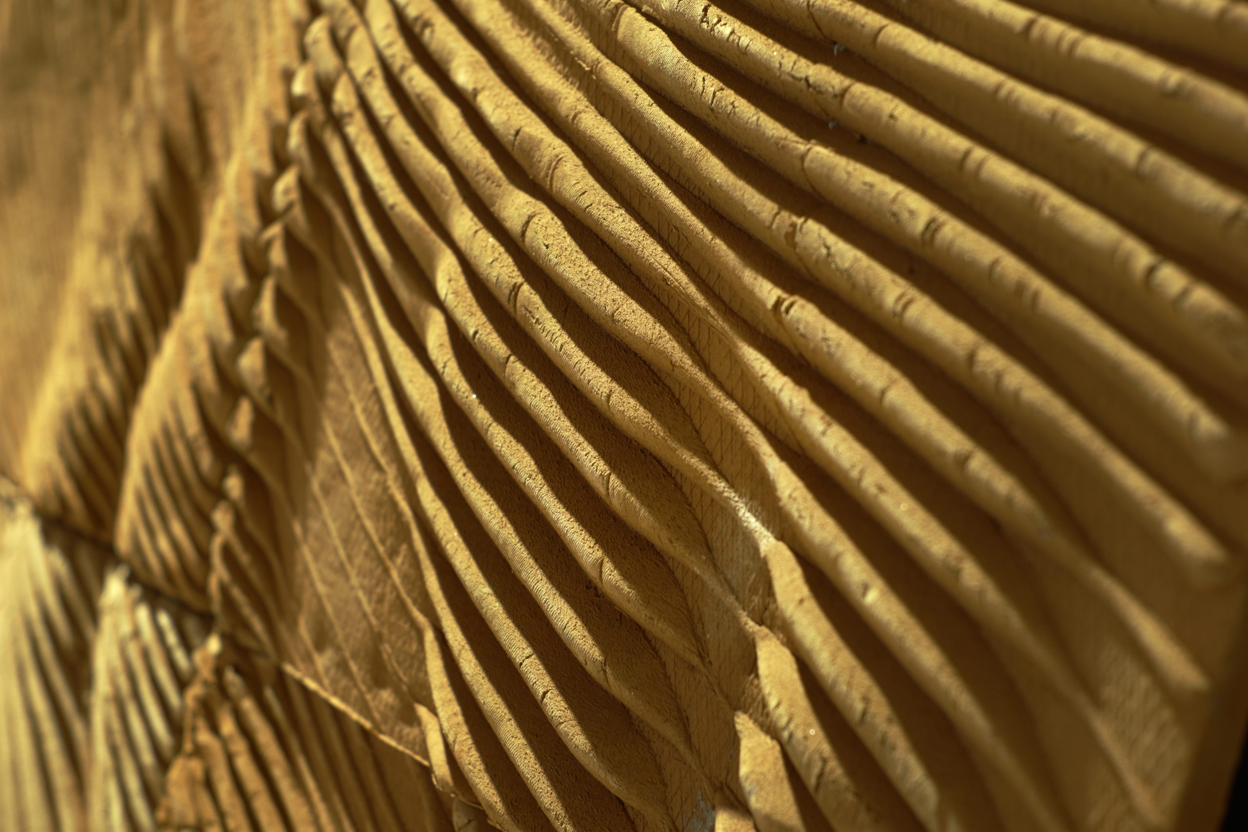
For the purposes of explaining the logic, an isosceles right triangle hotwire shape is used, oriented in a vertical plane, with the hypotenuse on the upper side and the right angle at the bottom (Fig. 1a). With a constant tool shape that generates the swept surfaces, the only thing that can be varied in the design phase is the tool path. For easier control of the final look, the parameters for the path are divided into those that direct the movement in the vertical and the horizontal plane. The vertical movement influences the depth of the ridges which in turn generates the relation between illuminated and shadowed parts (Fig 1b). In order to emphasize this relation in a more visual fashion, a reference image is used (Fig 1c), mapping the pixel intensity to the ridge depth. On the other hand, horizontal movement influences the flow of the ridges. Given that these ridges generate illumination distinctions, a larger number is preferable. More details on the design logic of using image pixels as depth indicator, as well as the process of generating guiding curves is explained in the next two sections.

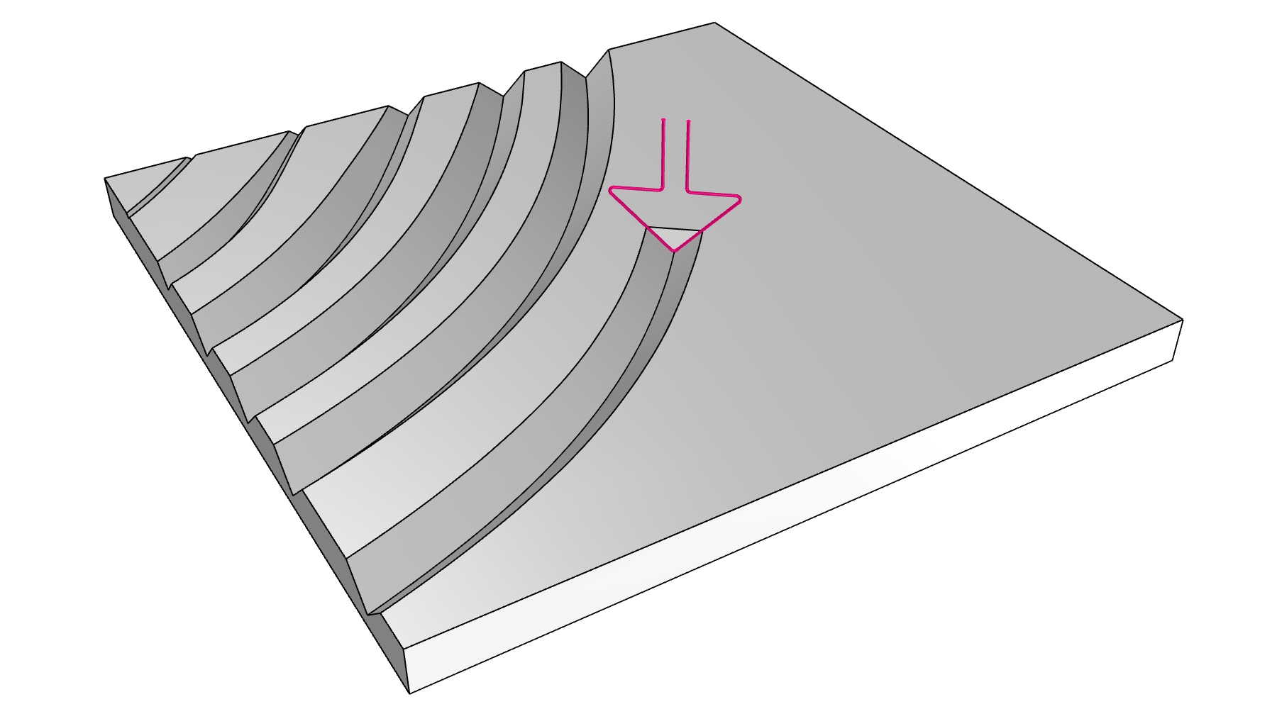
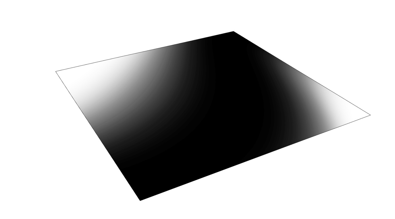
Figure 1. The elements used for generating ridges. a) Hotwire with shape of isosceles right triangle; b) Polystyrene block with representation of hotwire cutting process; c) Reference image mapping the pixel intensity to the ridge depth.
Subchapter 4.1 Depth indication
The notion of creating interesting works of art has to do with many features. One that is essential is definitely light – its presence or absence. Texture is one way of emphasizing this feature, making the piece different depending on the time of day or type of lighting. Up to the second half of the 20th century, creating works of art meant that there needed to exist a physical medium with which to paint on a canvas. However, with the presence of computers becoming ubiquitous, artistic pieces found their way on a computer monitor as well. Pixels became the main medium to transfer the light information, which consisted of color, brightness and saturation. The larger the number of pixels, the more comprehensive and clear the image was. Transferring all of this information to the real world was made easy through printing. Still, if a tactile nature wanted to be added to the piece, a method needed to be developed to map the information from the digital to the analogue domain.
One way that is used most often is mapping the pixel brightness or intensity to the depth parameter of a tactile element. In a perforated brick wall, this can be achieved by rotating the brick around their center mass axis to produce appropriate shadows (Gramazio and Kohler, 2009; Jovanovic et al, 2016a) (Fig 2a). Linear elements can be used in a similar fashion, with their inclination towards the main slab that holds them, producing the same result (Jovanovic et al, 2016b) (Fig 2b). Furthermore, the contrast the linear elements create in reference to the background can be utilized to generate an appropriate approximation of the reference image (Birsak et al, 2018; Jovanovic et al, 2019) (Fig 2c). This method is well established and versatile and hence can be used in the same manner. With this approach noted, the next thing is to define and establish the horizontal movement, which is done through the use of guiding curves.
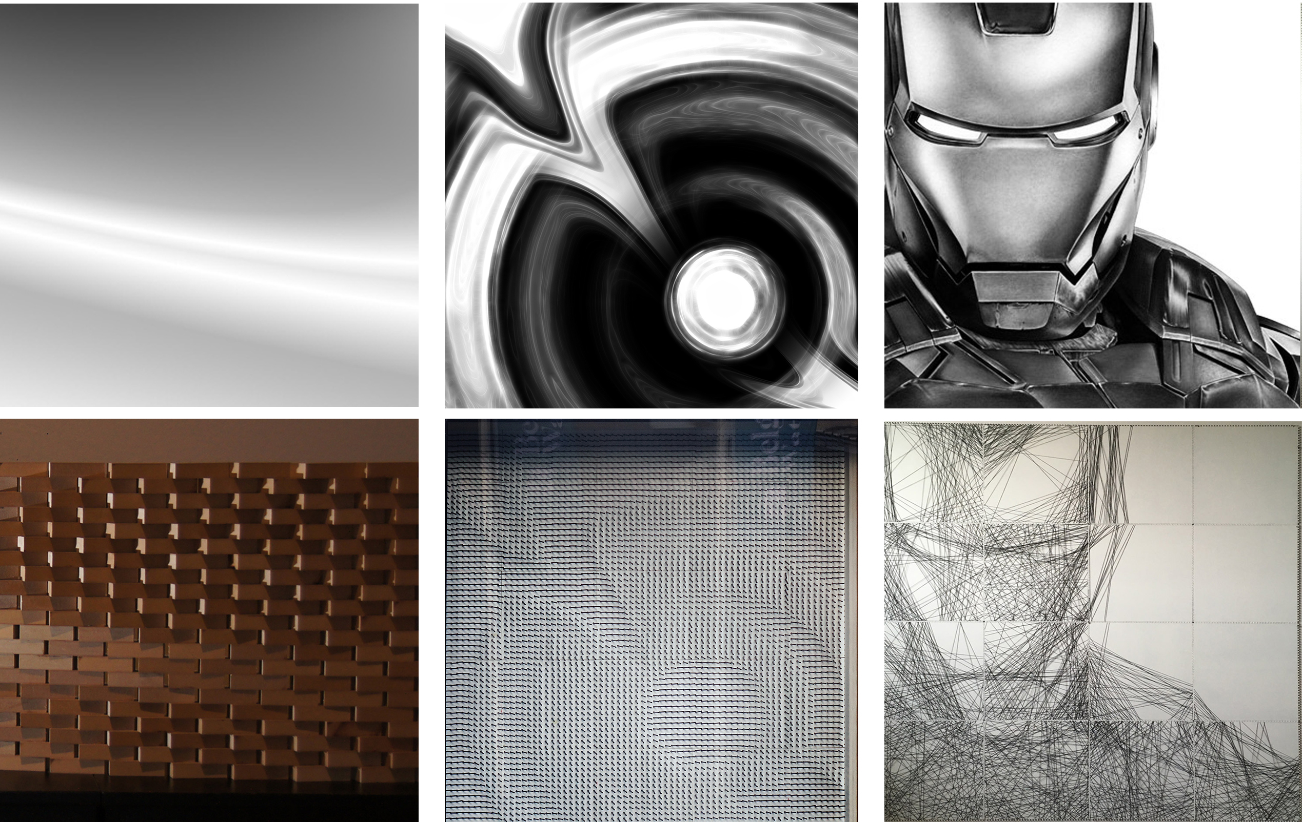
Figure 2. Samples mapping the pixel brightness. a) Perforated brick wall; b) Linear elements with inclination towards the main slab that holds them; c) The reference image which uses the contrast of linear elements in reference to the background.
Subchapter 4.2 Guiding Curves
The guiding curves (GC) are pathways that the industrial robot follows with the tip of the hotwire. In this case the tool is a planar triangular shape. In order to cut out the ridges, the tool plane is oriented perpendicularly to the tangent vectors of the GC. The easiest approach is to use equally spaced parallel lines, since the orientation of the tool remains the same (Fig 3a). In that manner, by increasing the ridge depth, its width gets larger and vice versa. The depth and width values have to be determined appropriately, otherwise, a larger portion of the polystyrene block can remain untouched between the lines and hence reduce the tectonics of the finished pieces. Parallel GC represents a more convenient way of representing images, given that the pixels are also arrayed within a grid of parallel lines. However, the fluency and tectonic nature is not fully explored by only using straight and parallel lines, which is why curved GC are explored as well.
The curved GC allows for a much more versatile interpretation of the reference image, given that their flow is not uniform. More precisely, the curved GC approach is not tied to only one curve being offset a specific amount of times (Fig 3b). While the process of creating a set of adequately spaced parallel lines is not difficult nor time-consuming, a set of curved GC can be both. The emphasis is to create distinct fluency, almost resembling magnetic vector fields around a myriad of randomly placed magnets in a plane. These curved GC can be drawn according to the image peculiarities or personal preferences (Fig 3c). To save up time, only a handful of curves can be generated in such a manner and the rest can be morphed in between a specific amount of time in reference to the maximum desired distance between the GC (Fig 3d). However, the distances between the curves are not constant in this case, which can be an issue for the perpendicular orientation of the tool. If not addressed appropriately, the tool can remove more material than necessary, even taking the surrounding portions and mitigating the representation of the initial image.
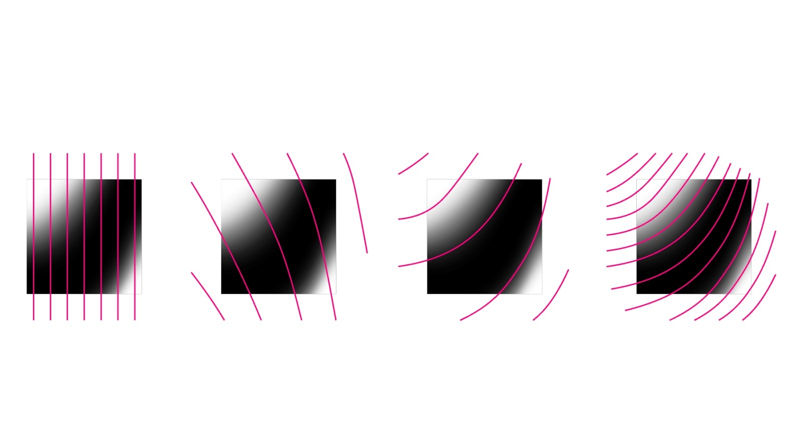
Figure 3. Samples of GC that the industrial robot follows with the tip of the hotwire. a) Equally spaced parallel vertical lines; b) Non-concentric curved lines; c) Arbitrarily lines; d) Non-concentric curved lines with small distances.
Hence, a vertical rotation of the tool plane is introduced, just enough so that the perpendicular projection of the rotated plane to the perpendicular plane does not go out of bounds i.e. does not coincide with the surrounding ridges (Fig 4). By introducing this condition, a fluent GC set can be generated fairly easily and in a short amount of time. If the distance between the curves is defined as a parameter, the amount of morphed curves can vary, thus producing either narrower ridges or more space in between them. Finally, the curves are trimmed to the size of the panel which matches the proportions of the reference image. With the GC defined it is possible to produce the final look of the polystyrene mold.
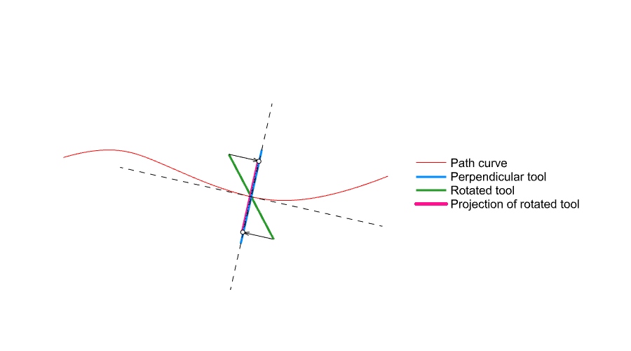
Figure 4. Representation of a vertical rotation of the tool plane, so that the perpendicular projection of the rotated plane to the perpendicular plane does not coincide with the surrounding ridges.
Subchapter 4.3 Integration
The integration phase takes into account the shape and orientation of the tool and the parameters associated with the vertical and horizontal movement. In order to produce the final mold look, the paths need to be determined and subsequently the orientation of the hotwire tool along the path.
The path consists of moving in both vertical and horizontal planes. In order to integrate both, the GC is approximated by a set of equally spaced points (Fig 5a). These points need to take information from the reference image in order to be moved vertically down and later interpolated into a final GC. Hence, the points are reparametrized as UV coordinates on the panel surface (Fig 5b). Given that the reference image has the same proportions as the surface, these UV points sample pixels, located at the same coordinates, and return the pixel intensity in return. Once all the values are sampled, a bounds domain is created and remapped according to a desired domain in order to determine the maximum value of vertical movement i.e. depth. This value influences the ridge width and indirectly the tool orientation, so is a relevant factor. Once the vertical movements are defined, they are used to move the GC points downwards, after which the points are used to create an interpolated curve through them, thus generating the final GC path (Fig 5c).
Given that the final GC can be too close to one another and cause issues, as explained earlier, the tool orientation needs to be addressed as well. A perpendicular orientation to the GC tangent vector is set as default and then modified according to the following condition – rotate the tool plane enough to avoid the hotwire curve from overstepping the half distance between the two neighboring GC (Fig 5d). In such a way, the unwanted material subtraction is avoided. Finally, by creating a swept surface through the curves located in adequately oriented planes along the GC, ridge-like geometry is formed (Fig 5e). By capping it, solids are created which are used through boolean difference functions to remove portions of a polystyrene block model and produce the final look (Fig 5f). Once the final mold look is aesthetically pleasing, the fabrication stage can commence.
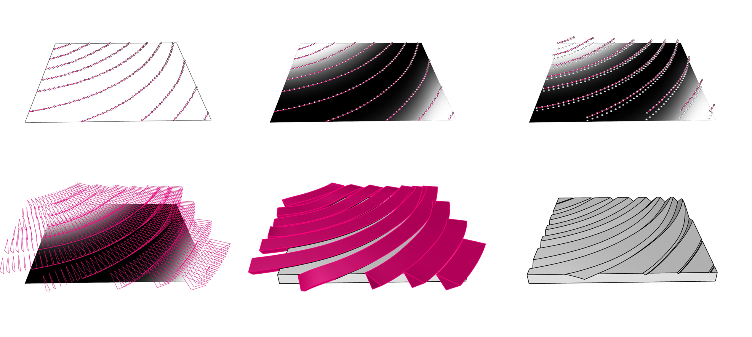
Figure 5. The process of creating mold in a software application. a) The GC approximated by a set of equally spaced points; b) Reparametrization of points as UV coordinates on the panel surface; c) Generating the final GC path; d) Representation of hotwire positions; e) Ridge-like geometry is formed by generating a swept surface through the curves; f) Creating the mold by using boolean difference functions.
Chapter 5. Fabrication
Teaching method: Workshop
Duration: 120 min
Usually, a 3D model is the input for the fabrication phase involving 3D printing or CNC milling, where specific software analyzes the data and produces adequate paths for its generation. However, in this case, the finished digital model merely showcases how the end result will look. The real input is located in the orientation and position of the hotwire tool, procured a couple of steps before the final model is obtained. By preparing this type of data, it is possible to give proper instructions to the robot which in turn should produce the outcome that the digital 3D model is showing. However, this all has to do with the digital fabrication process using an industrial robot. The clay, as the material being used, has a vernacular history and nature to it and has to be adapted to the different fabrication approach. This is why it is important to analyze the traditional manner of creating clay components and adjust or elevate it through contemporary means of using digital design tools, techniques and manufacturing processes.
Subchapter 5.1 Traditional (analogue) approach
Using earth, mixed with water, shaping it to preference and letting it dry in the air before casting it in the fire to be baked is a perfect illustration of the natural order. The four main elements of life are connected in this process and by following it, varying shapes have been created throughout the millennia. Some have relied on their hands to sculpt organic and fluent forms, while others have used molds, which works well for bricks for example. Brick molds are uniform and rigid as opposed to the molds used in this workshop, which portray fluency, idiosyncrasy and customization.
Whatever the shape may be, the clay extraction process remains the same. Once moist clay is delivered to the sculpting studio, it is hydrated in a specific ratio and extruded into long cylindrical shapes. The sculpting studio maintains a constant temperature and humidity to avoid uneven or unpredicted material behavior. These cylinders are 50cm in length and 10cm in diameter. Before the cylinders are sculpted into desired shapes they are kept damped under foiled sheets to prevent them from losing moisture. Once a cylinder is chosen for sculpting, its consistency is almost homogenous pending the extrusion process it underwent. Hence, removing any material from the cylinder does not generate additional fractures or cracks on the surface. Only by adding clay material is such an endeavor possible, which can lead to the fracture drying at a different rate and causing clay component fracture and eventual breakage later on. This is why it is important to avoid adding material to the piece when working. Furthermore, avoiding direct contact of the human skin with the clay is preferable since it can cause a buildup of minerals from the human sweat which after baking shows as white stains on the clay component.
After a clay component has been shaped, it needs to be left to dry, so that excess moisture can evaporate. Otherwise, a high level of moisture can create a huge pressure inside of the clay component during the baking process that can lead to explosions inside the furnace. Hence a significant time portion needs to be allocated to the drying stage, which depends on the sculpting studio conditions and size of the clay component being made. Since the air drying process requires the clay casted element to be left to dry with as much surface area showing as possible, the clay material cannot remain in the mold and has to be taken out right after the shaping has taken place. All these aspects need to be taken into consideration, since they directly influence the mold casting or shaping process later on. It was once said that tradition is an arrow pointed towards the future. By knowing where we have been, we know where to point ourselves to. By knowing the traditional way, we can honor it, but also find ways to insert the contemporary means of achieving smooth shaped elements with digital fabrication.
Subchapter 5.2 Contemporary (digital) approach
By following the design logic guidelines regarding fabrication, the orientation and position of the hotwire profile curve are taken as the most important to drive the mold generation. Given that the model generation refers to a real physical model, a transition from a virtual to a real world environment needs to occur. In order to do so, it is necessary to generate a set of instructions that the robot can follow. The instructions are written by using “targets”. Targets represent both the position and orientation of the end effector of the industrial robot arm, which carries the hotwire profile tool (Fig 6a). By using inverse kinematics, it is possible to calculate the angles in the industrial robot joints as it moves from one target to the other. Additional targets had to be added to the existing ones on the flow lines in order to allow the hotwire tool to exit the polystyrene block that it is cutting and enter the block at a new location (Fig 6b). This phase also entails simulating the robot in order to verify if all the targets are within the robot’s work area, if all the joint angles are within the proper domains and that there are no collisions between the robot with itself and the surrounding (Fig 6c). After the instructions have been generated and verified it is possible to transition to the polystyrene mold fabrication.
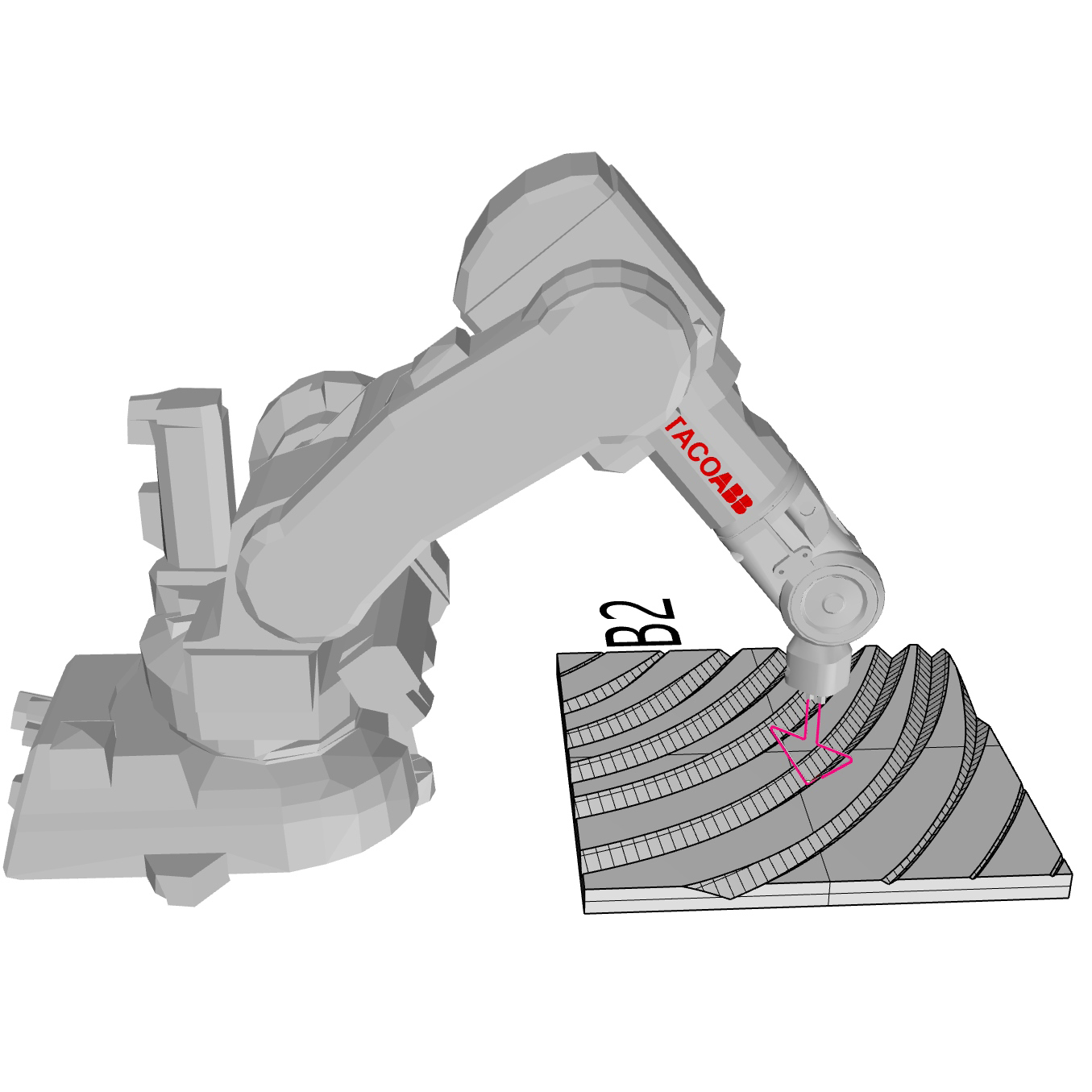
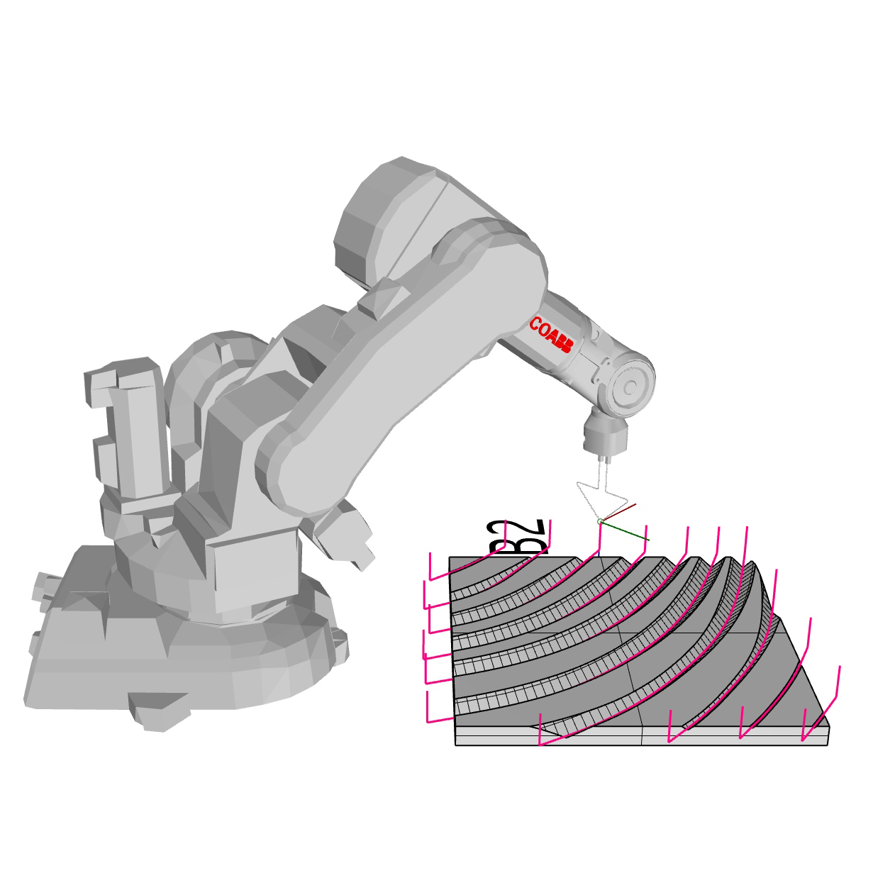
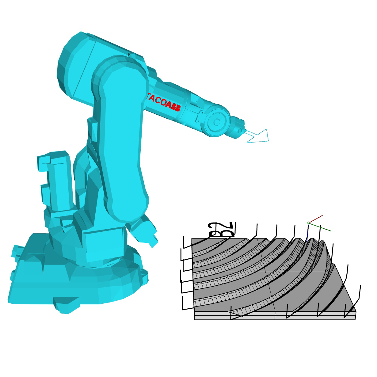
Figure 6. Virtual representation of robotic arm with hotwire tool: a) inside the mold; b) outside the mold; c) outside the mold to verify that joint angles are within the proper domains.
Polystyrene blocks, 5 cm thick, were chosen for this task, out of which 50x33cm panels were cut out. The panels were oriented in front of the industrial robot arm, on a horizontal table so that the hotwire profile tool can access it on the upper side (Fig 7a). The hotwire temperature is set from 300 to 350°C, with the speed being between 5 and 10 mm/s depending on the contact area and the material. These parameters are changed manually. Given the fact that the hotwire radiates heat, the residual temperature influences the generation of artifacts, which are seen as curled up ends of the grooves’ sides (Fig 7b). The existence of artifacts is undesirable, since their shape is concave with respect to the direction of the clay extraction from the mold. This makes the clay casting process difficult, which is why these artifacts are sanded off the grooves. Once the grooves are prepared for clay casting, the panel sides are boarded up in order to shape the border adequately (Fig 7c).
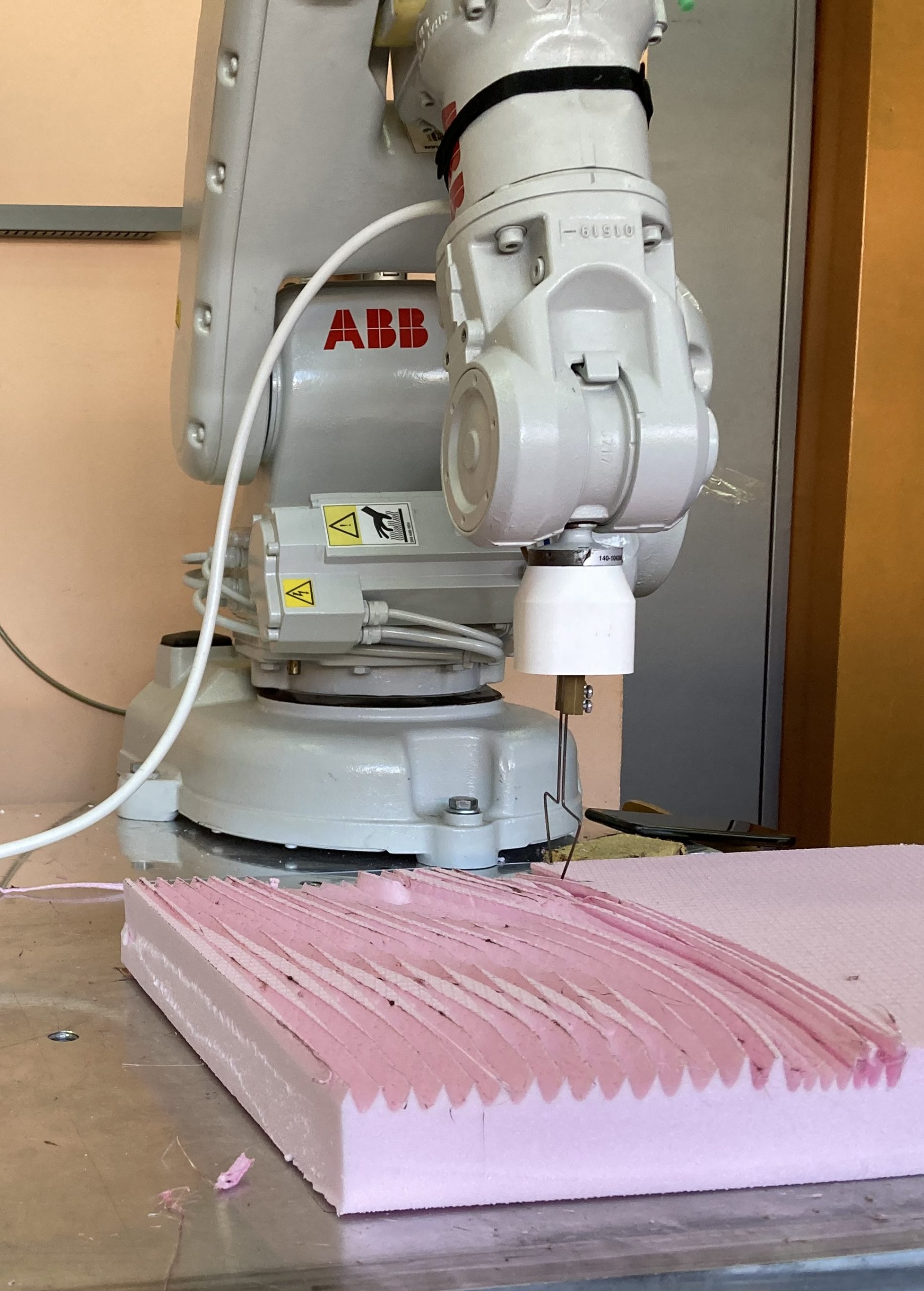
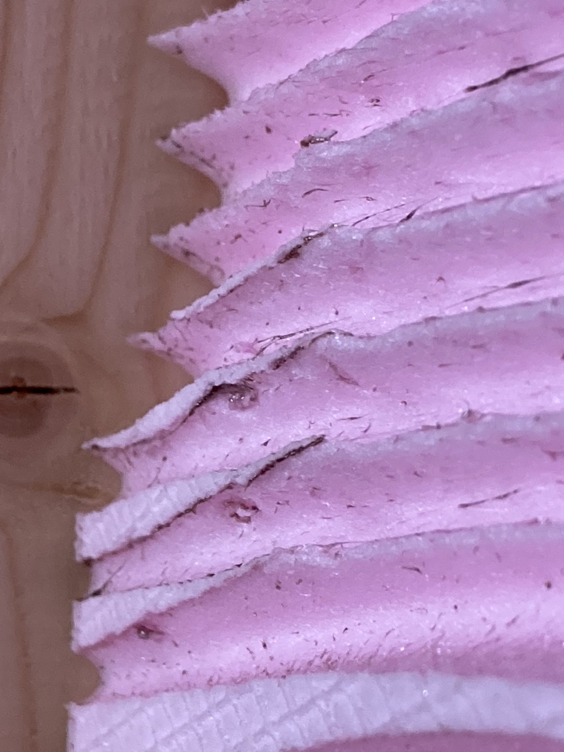
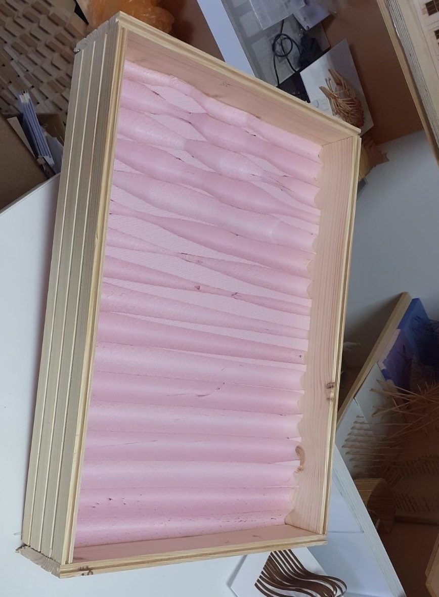
Figure 7. Preparing molds for embedding the clay. a) Cutting process of polystyrene block; b) Artifacts on the grooves’ sides; c) The boarding up of panel sides to create a final mold.
Subchapter 5.3 Integration
In the last phase, the emphasis is placed on the clay, starting with embedding the clay into the mold. If clay is embedded in pieces, the formation of cracks can occur due to the properties of the material. This is why prior to the embedding process, the clay is pressed into a shape resembling a pancake, with constant thickness of 2cm, out of which the necessary dimensions of the panel, 50x33cm are cut out (Fig 8a). After embedding this piece of clay, additional clay is added in order to procure a thickness of 3 cm in total. In order to make the process of clay extraction more efficient, sanded pieces of terracotta are dusted on the panel, prior to the embedding process. Immediately after the embedding process, the side boards are removed and the embedded clay is extracted from the mold (Fig 8b). The clay panels are left to dry for around two weeks in conditions of constant temperature and humidity, to remove excess water from the clay. This process is necessary due to the final step, which is baking them in a furnace at 980°C for 48 hours, where any excess of water can produce steam and explode the clay element inside the furnace. Once the panels are baked, they are ready to be placed on the wall as an interior panel (Fig 8c).
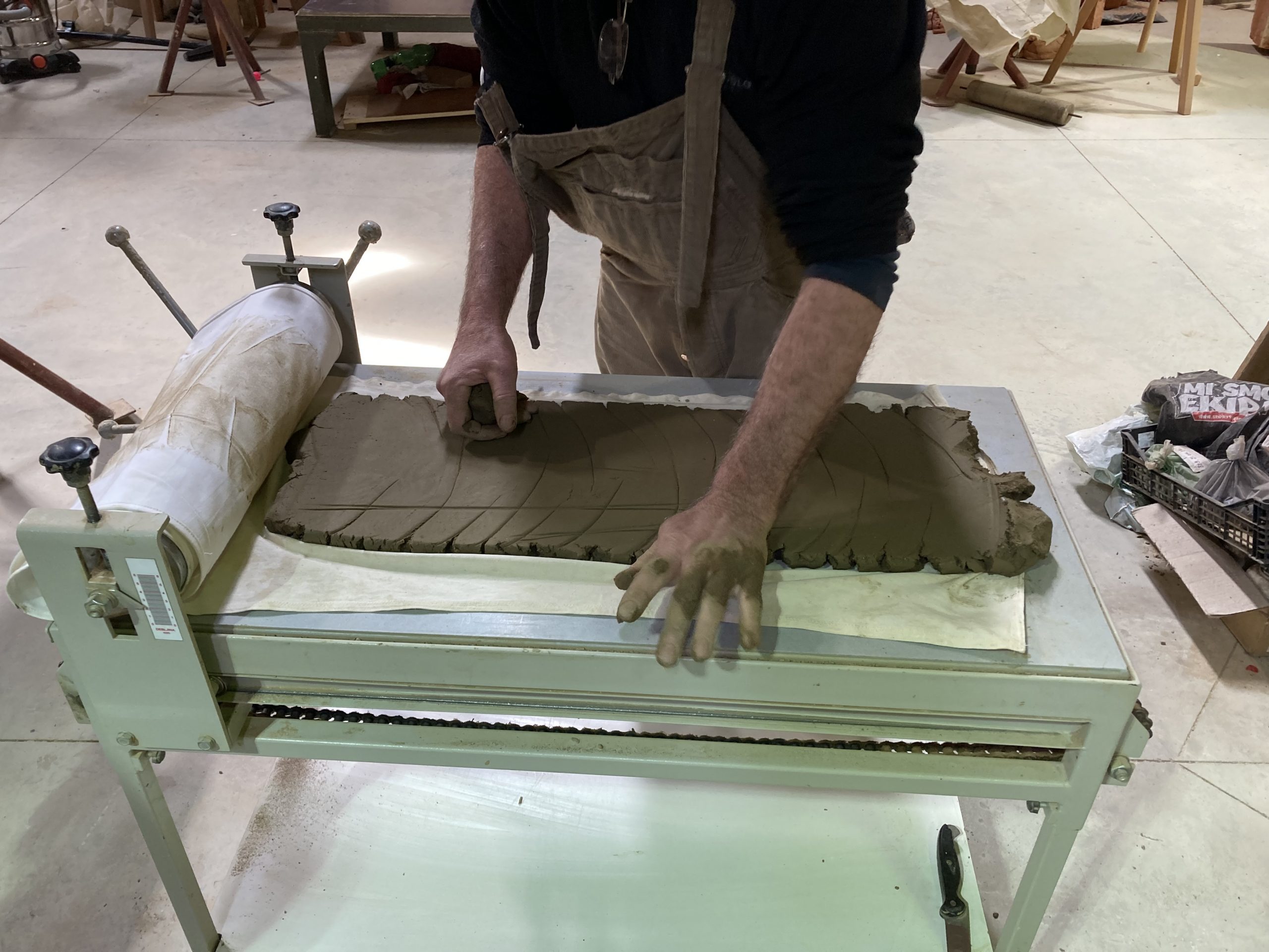
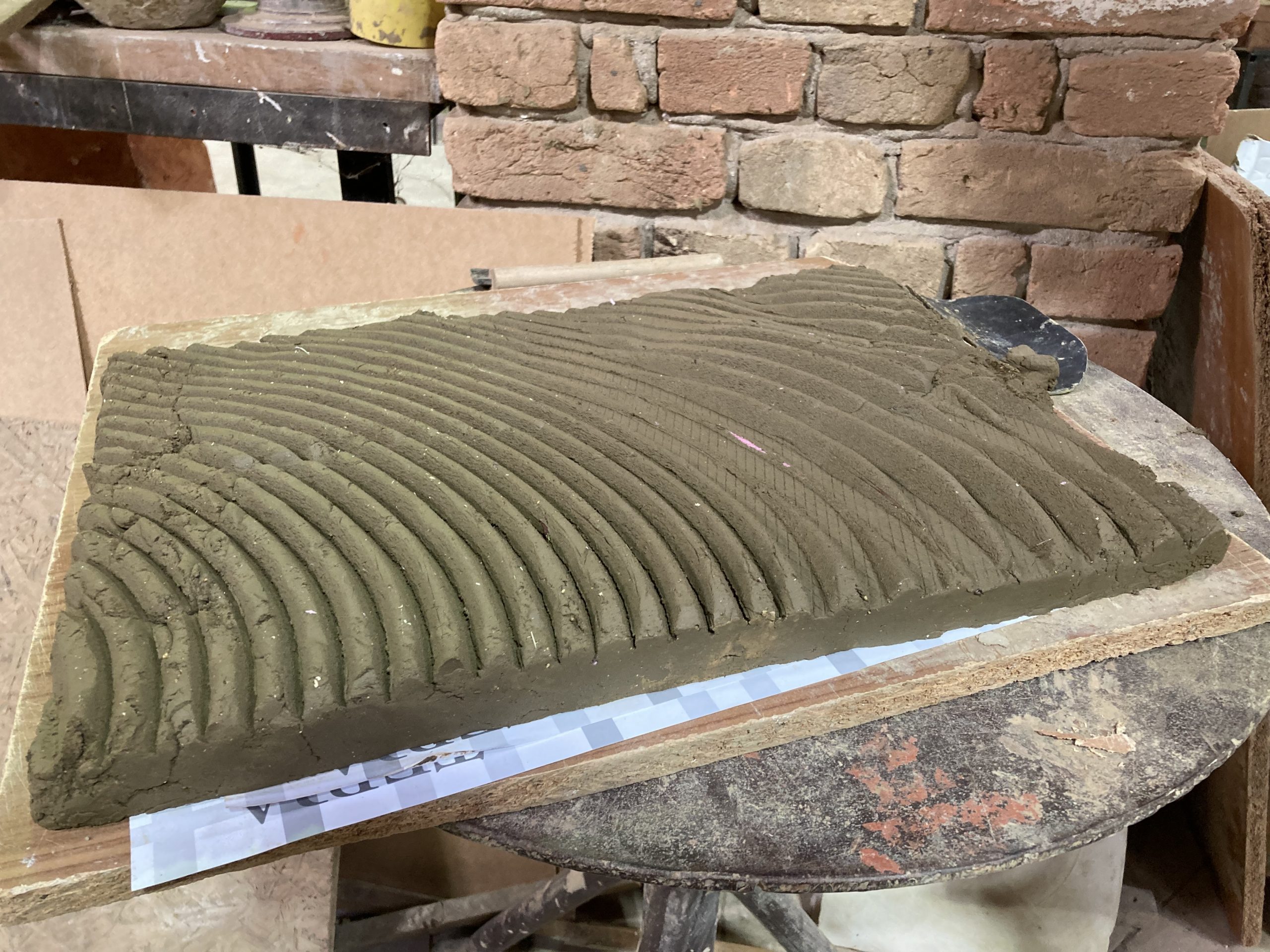
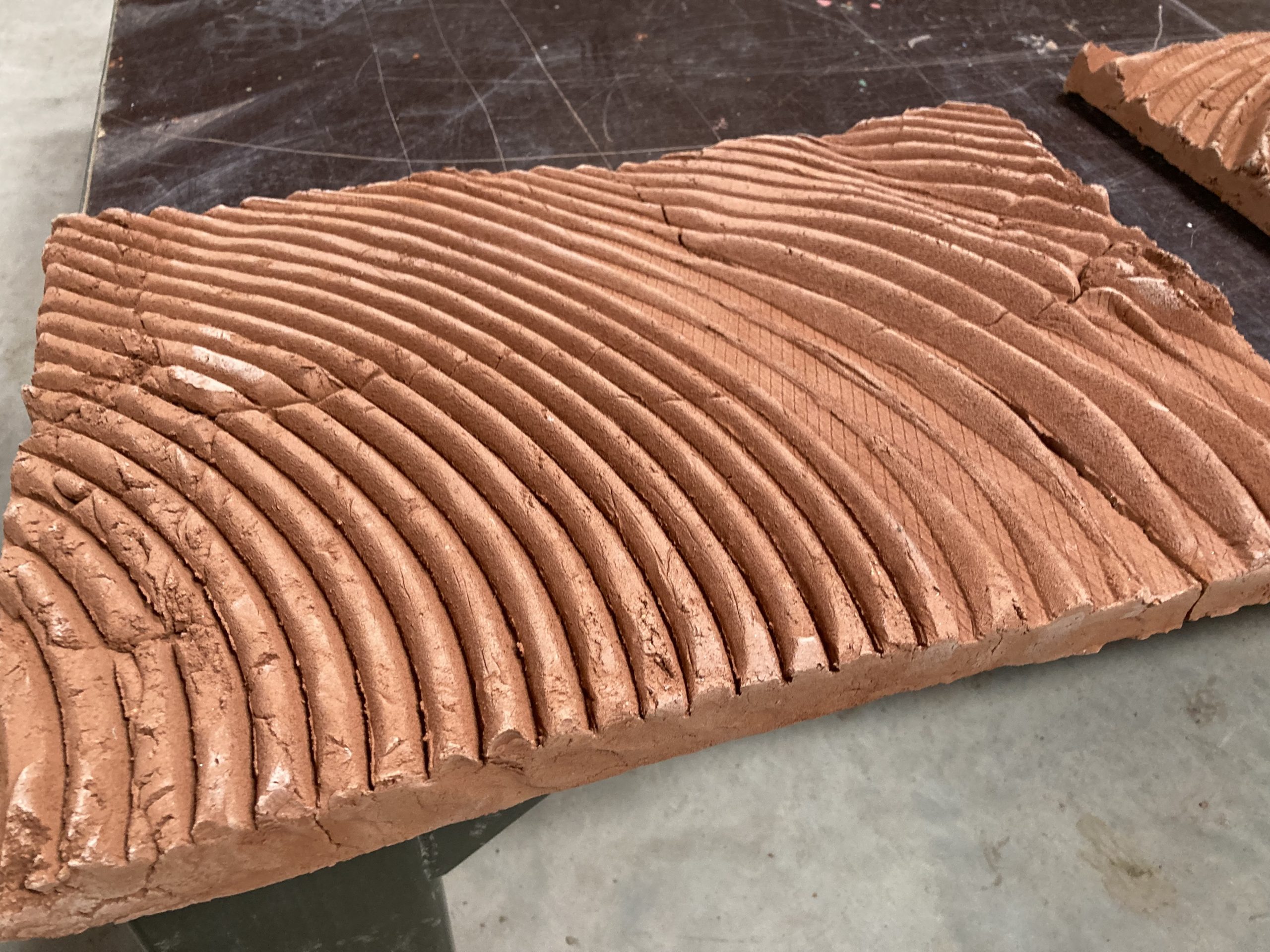
Figure 8. Creation of final clay panels. a) Pressing the clay into the shape of the panel; b) Extracting the clay from the mold; c) Baked and dried panel.
References
- Grafton, A., 2002. Leon Battista Alberti: Master Builder of the Italian Renaissance. Harvard University Press.
- Brunelleschi, F. and Battisti, E., 1981. Filippo Brunelleschi: The Complete Work. Rizzoli International.
- Moe, K., 2008. Integrated design in contemporary architecture. Princeton Architectural Press.
- Wong, K.D. and Fan, Q., 2013. Building information modelling (BIM) for sustainable building design. Facilities. ISSN: 0263-2772. pp. 138-157. doi: 10.1108/02632771311299412
- Preidel, C., Borrmann, A., Oberender, C. and Tretheway, M., 2017. Seamless integration of common data environment access into BIM authoring applications: The BIM integration framework. In eWork and eBusiness in Architecture, Engineering and Construction (pp. 119-128). CRC Press.
- Leach, N. and Yuan, P.F., 2019. Computational Design. Tongji University Press.
- Gerber, D.J., Lin, S.H.E., Pan, B.P. and Solmaz, A.S., 2012, March. Design optioneering: multi-disciplinary design optimization through parameterization, domain integration and automation of a genetic algorithm. In Proceedings of the Symposium on Simulation for Architecture and Urban Design (Vol. 11). pp. 23-30.
- Gramazio, F. and Yoon, J.M., 2018, November. Digital materiality in architecture. In The William Cooper Mack Thesis Fellowship Lecture (2018).
- Gramazio, F., Kohler, M., Willmann, J. and Langenberg, S., 2012. Digital by Material. Envisioning an Extended Performative. ROB ARCH Conference 2012-Robotic Fabrication in Architecture, Art and Design, Rotterdam, Stuttgart, Graz, Zurich, Vienna, December 17-18. pp. 13-105.
- Wortmann, T. and Schroepfer, T., 2019. From optimization to performance-informed design. SIMAUD ’19: Proceedings of the Symposium on Simulation for Architecture and Urban Design. 1-8
- Gramazio, F. and Kohler, M., 2009. Facade Gantenbein Winery. Urban Flux. Art and Design Publishing House, Volume 8, pp.88-91.
- Yunis, L., Kyjánek, O., Dörstelmann, M., Prado, M., Schwinn, T. and Menges, A., 2014. Bio-inspired and fabrication-informed design strategies for modular fibrous structures in architecture. Proceedings of the 32nd eCAADe Conference – Volume 1, Department of Architecture and Built Environment, Faculty of Engineering and Environment, Newcastle upon Tyne, England, UK, 10-12 September, pp. 423-432. doi: 10.52842/conf.ecaade.2014.1.423
- Pigram, D. and McGee, W., 2011. Formation Embedded Design: A methodology for the integration of fabrication constraints into architectural design. ACADIA 11: Integration through Computation [Proceedings of the 31st Annual Conference of the Association for Computer Aided Design in Architecture (ACADIA)] [ISBN 978-1-6136-4595-6] Banff (Alberta) 13-16 October, pp. 122-131. doi: 10.52842/conf.acadia.2011.122
- Creang, E., Ciotoiu, I., Gheorghiu, D. and Nash, G., 2010. Vernacular architecture as a model for contemporary design. WIT Transactions on Ecology and the Environment, 128, pp.157-171. doi: 2495/ARC100141
- Sabin, J.E., 2010. Digital Ceramics: Crafts-based Media for Novel Material Expression & Information Mediation at the Architectural Scale. ACADIA 10: LIFE in:formation, On Responsive Information and Variations in Architecture [Proceedings of the 30th Annual Conference of the Association for Computer Aided Design in Architecture (ACADIA) ISBN 978-1-4507-3471-4] New York 21-24 October, pp. 174-182. doi: 10.52842/conf.acadia.2010.174
- Van Herat, O. 2014: “Functional 3D Printed Ceramics, Explorations in functional 3D Printing Ceramics”. Available from: http://oliviervanherpt.com/functional-3d-printed-ceramics/ (accessed November 2015)
- Kontovourkis, O. and Tryfonos, G., 2018. Integrating parametric design with robotic additive manufacturing for 3D clay printing: An experimental study. In ISARC. 35th International Symposium on Automation and Robotics in Construction. Vol. 35, pp. 1-8).
- Kontovourkis, O. and Tryfonos, G., 2020. Robotic 3D clay printing of prefabricated non-conventional wall components based on a parametric-integrated design. Automation in Construction, 110, p.103005. doi: 10.1016/j.autcon.2019.103005
- Anton, A. and Abdelmahgoub, A., 2018. Ceramic components-computational design for bespoke robotic 3D printing on curved support. Proceedings of the 36th International Conference on Education and Research in Computer Aided Architectural Design in Europe (eCAADe) [Volume 2].pp 71-78.
- Rosenwasser, D., Mantell, S. and Sabin, J., 2017. Clay non-wovens: robotic fabrication and digital ceramics. ACADIA 2017: DISCIPLINES & DISRUPTION Proceedings of the 37th Annual Conference of the Association for Computer Aided Design in Architecture (ACADIA) ISBN 978-0-692-96506-1 Cambridge, MA 2-4 November, pp. 502- 511. doi: 10.52842/conf.acadia.2017.502
- Tan, R. and Dritsas, S., 2016. Clay robotics: tool making and sculpting of clay with a six-axis robot. Living Systems and Micro-Utopias: Towards Continuous Designing, Proceedings of the 21st International Conference on Computer-Aided Architectural Design Research in Asia (CAADRIA 2016) / Melbourne 30 March–2 April, pp. 579-588. doi: 10.52842/conf.caadria.2016.579
- Guo, Z., Zhang, Z. and Li, C., 2022. Robotic Carving Craft, Research on the Application of Robotic Carving Technology in the Inheritance of Tradition-Al Carving Craft. POST-CARBON – Proceedings of the 27th CAADRIA Conference, Sydney, 9-15 April, pp. 747-756.
- Ma, Z., Duenser, S., Schumacher, C., Rust, R., Baecher, M., Gramazio, F., Kohler, M. and Coros, S., 2021. Stylized robotic clay sculpting. Computers & Graphics, 98, pp.150-164. doi: 10.1016/j.cag.2021.05.008
- Jovanović, M., Raković, M., Tepavčević, B., Borovac, B. and Nikolić, M., 2017. Robotic fabrication of freeform foam structures with quadrilateral and puzzle shaped panels. Automation in Construction, 74, pp.28-38. doi: 10.1016/j.autcon.2016.11.003
- Jovanovic, M., Vucic, M., Mitov, D., Tepavcevic, B., Stojakovic, V., & Bajsanski, I. 2017. Case Specific Robotic Fabrication of Foam Shell Structures. Proceedings of the 35th International Conference on Education and Research in Computer Aided Architectural Design in Europe (eCAADe), Volume 2 .pp 135-142. doi: 10.52842/conf.ecaade.2017.2.135
- Jovanovic, M., Vucic, M., Štulić, R., & Petrovic, M. 2019. Design Guidelines for Zero Waste Manufacturing of Freeform EPS Facades. Proceedings of the 37th International Conference on Education and Research in Computer Aided Architectural Design in Europe (eCAADe) & 23rd Conference of the Iberoamerican Society Digital Graphics, Volume 2 . pp. 779-788. doi: 10.5151/PROCEEDINGS-ECAADESIGRADI2019_345
- Rust, R., Jenny, D., Gramazio, F., & Kohler, M. (2016). Spatial Wire Cutting: Cooperative robotic cutting of non-ruled surface geometries for bespoke building components. CAADRIA proceedings. pp. 529-538. doi: 10.52842/conf.caadria.2016.529
- Søndergaard, A., Feringa, J., Nørbjerg, T., Steenstrup, K., Brander, D., Graversen, J., Markvorsen, S., Bærentzen, A., Petkov, K., Hattel, J. and Clausen, K., 2016. Robotic hot-blade cutting. In Robotic fabrication in architecture, art and design. pp. 150-164. Springer, Cham.
- Yabanigül, M.N. and Yazar, T., 2021. Production of Gyroid-like modular systems with non-linear robotic hotwire cutting. Automation in Construction, 126, p.103671.doi: 10.1016/j.autcon.2021.103671
- Jovanovic, M., Stojakovic, V., Tepavcevic, B., Mitov, D. and Bajsanski, I., 2016. Generating an anamorphic image on a curved surface utilizing robotic fabrication process. Herneoja, Aulikki; Toni Österlund and Piia Markkanen (eds.), Complexity & Simplicity – Proceedings of the 34th eCAADe Conference – Volume 1, University of Oulu, Oulu, Finland, 22-26 August, pp. 185-191. doi: 52842/conf.ecaade.2016.1.185
- Jovanović, M., Tasevski, J., Tepavčević, B., Raković, M., Mitov, D. and Borovac, B., 2016, June. Fabrication of digital anamorphic sculptures with industrial robot. In International Conference on Robotics in Alpe-Adria Danube Region (pp. 568-575). Springer, Cham. doi: 10.1007/978-3-319-49058-8_62
- Birsak, M., Rist, F., Wonka, P. and Musialski, P., 2018, May. String art: towards computational fabrication of string images. In Computer Graphics Forum. Volume 37. No. 2, pp. 263-274.
- Jovanović, M., Vučić, M., Tepavčević, B., Raković, M. and Tasevski, J., 2019, June. Robotic Knitting in String Art as a Tool for Creative Design Processes. In International Conference on Robotics in Alpe-Adria Danube Region. pp. 179-187. Springer, Cham. doi: 10.1007/978-3-030-19648-6_21
Other Instructors

Bojan TEPAVČEVIĆ
Associate Professor

Marko VUČIĆ
Assistant Professor

Marko JOVANOVIĆ
Assistant Professor

Ivana BAJŠANSKI
Assistant Professor

Vesna STOJAKOVIĆ
Associate Professor
Syllabus
The course presents a review of the digital interpretation of clay products and their fabrication using robotics. During most of its architectural history, clay products have been fabricated and used mainly as modular elements of the same dimensions. The advent of computational and digital fabrication tools in modern architectural practice opened the possibility for clay products customization. After reviewing the situation in the field and different approaches to solving this problem, this course will present a workflow that deals with the design of clay panels according to fabrication logic and limitations, programming of the industrial robotic arm, as well as fabrication of Styrofoam molds and clay casting. Computational design tools change the approach to the design and fabrication of clay products, which is especially important for the Banat region, where this industry is quite ubiquitous, and the architecture is based on clay products.
O1.M3 INTERPRETING AND WORKING ON HERITAGE OBJECTS IN THEIR LANDSCAPE
O1.M3.03.02 Digital fabrication for clay based structures
Type of format
Lecture & workshop
Duration
30 min lecture (theoretical notions) 15 min break 45 min lecture (exemplification) 15 min break 60 min workshop (design) 15 min break 60 min workshop (fabrication 1/2) 15 min break 60 min workshop (fabrication 2/2)
Possible connections (with other schools / presented topics)
UNS O1. M3.03.01 UNS / Computational design for clay based structures DEB O1. M3.01. DEB /Recognition by small scale intervention
Main purpose & objectives
The aim of the course is to encourage students to apply digital tools, especially robotics, in the area of fabricating clay products with complex geometry. Another aim is to induce more contemporary approaches in clay utilisation, since nowadays novel artificial materials and technologies are overwhelmingly traditional and natural ones. However, in this exploration module, the emphasis is placed on several areas of interest: ● Design strategies for customised relief clay panels ● Robotic fabrication with custom tool ● Fabrication strategies for customised relief clay panels
Skills acquired
Detailed theoretical knowledge about contemporary design approaches related to clay forming, based on material and structural logic as well as design and manufacturing processes. Upgraded skills in the Grasshopper and Rhinoceros3D software environment, as well as TacoABB add-on specified for ABB Industrial robot fabrication. Students will acquire knowledge of clay casting in the customised and various unique shaped Styrofoam molds.
Contents and teaching methods
1. Integrated Design Approach 2. Informed design 3. Digital Ceramics 3.1. State of the Art 3.2. A Novel Approach 4. Design Logic: 4.1. Depth indication 4.2. Guiding Curves 4.3. Integration 5. Fabrication: 5.1. Traditional (analogue) approach 5.2. Contemporary (digital) approach 5.3. Integration.
Reviews
Lorem Ipsn gravida nibh vel velit auctor aliquet. Aenean sollicitudin, lorem quis bibendum auci elit consequat ipsutis sem nibh id elit. Duis sed odio sit amet nibh vulputate cursus a sit amet mauris. Morbi accumsan ipsum velit. Nam nec tellus a odio tincidunt auctor a ornare odio. Sed non mauris vitae erat consequat auctor eu in elit.
Members
Lorem Ipsn gravida nibh vel velit auctor aliquet. Aenean sollicitudin, lorem quis bibendum auci elit consequat ipsutis sem nibh id elit. Duis sed odio sit amet nibh vulputate cursus a sit amet mauris. Morbi accumsan ipsum velit. Nam nec tellus a odio tincidunt auctor a ornare odio. Sed non mauris vitae erat consequat auctor eu in elit.